2 - 54 Conversational Part Programming v546CO WinMax Lathe Conversational Part Programming
Geometry
Define the shape of the groove using the fields in the Geometry tab.
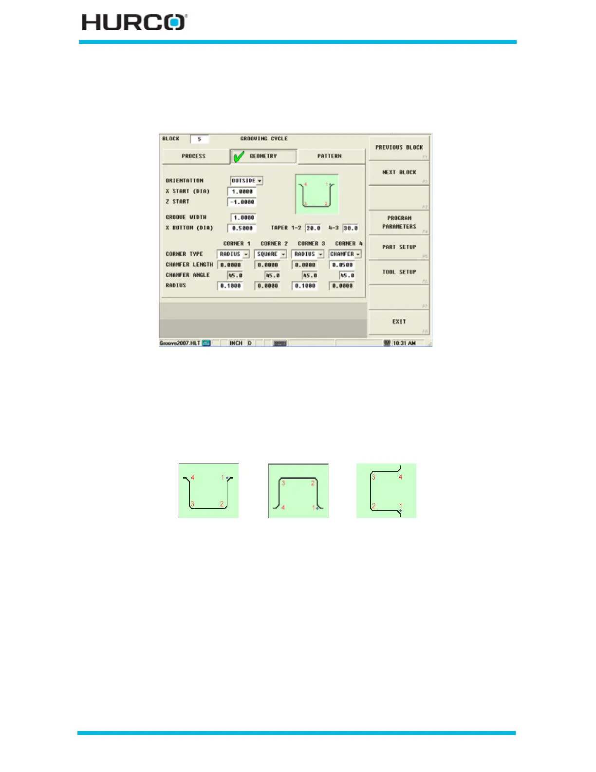
Figure 2–44. Grooving Cycle Geometry Tab screen
Use these fields to program the shape of the groove:
• ORIENTATION—select among Outside, Inside, and Face for the groove
type. The on-screen graphic changes to represent the orientation for each
selection.
Figure 2–45. Groove Orientation selections
• X START (DIA) or RAD)—identifies the X axis starting location for the
Grooving cycle. The tool begins cutting at the programmed feedrate at this
location. Change between Diameter and Radius by selecting the D or R in the
status bar. This dimension is shown as 2 in the following figure.
• Z START—identifies Z axis starting location for the Grooving cycle. The tool
begins cutting at the programmed feedrate at this location. This dimension is
shown as 4 in the following figure.
• GROOVE WIDTH—indicates how wide the Groove needs to be. This
dimension is shown as A in the following two figures.
Outside
Inside Face
 Loading...


