WinMax Lathe Conversational Part Programming v546CO Conversational Part Programming 2-115
Radial Hole Cycle
From the New Radial Holes Operation screen, select Radial Hole Cycle F1. The Radial
Holes Drill screen appears.
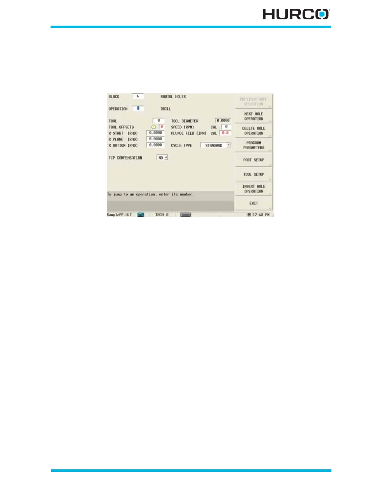
Figure 2–96. Live-Tooling Radial Holes Drill Operation screen
The fields on this screen are defined as follows:
• TOOL—identifies the tool number that will be used in the part program.
• TOOL OFFSETS—identifies the tool offset and orientation programmed in
Tool Setup that will be used. The tool offset defaults to the same number as
the tool.
• X START (DIA) or (RAD)—defines the point, relative to the surface of the
part, where the tool moves when starting the cycle, before moving at Rapid
to the R Plane.
• R PLANE (DIA) or (RAD)—defines an absolute position, relative to the
surface of the part. The cycle will rapid to this location before feeding to X
Bottom.
• X BOTTOM (DIA) or (RAD)—identifies the depth of the hole, relative to the
surface of the part when Linear is selected in the Coordinates field of the
Radial Locations screen, and relative to the centerline when Rotary is
selected. This field is automatically adjusted for the drill tip if YES is selected
for Tip Compensation.
• TIP COMPENSATION—accesses YES or NO selections to indicate whether
the tool tip is included as part of the Z Bottom measurement. This field
appears when the tool is a live drill or a live center drill. Z Bottom depth is
automatically calculated for the drill tip when YES is selected and is based on
the drill tip angle programmed in Tool Setup.
• TOOL DIAMETER—contains the tool diameter programmed in Tool Setup for
the current tool. This field is read-only and can only be edited in Tool Setup.
 Loading...


