WinMax Lathe Conversational Part Programming v546CO Conversational Part Programming 2-105
Geometry Tab
Finishing follows the geometry of the contour defined in the Geometry tab.
Finishing follows the geometry of the contour defined in the Geometry tab. The fields on
the Geometry tab are defined as follows:
• CYLINDER DIAMETER or RADIUS—defines the diameter or radius of the
cylinder.
• COORDINATES—defines the coordinates as either Linear or Rotary.
• Linear coordinates are used when working from a flat drawing. When
Linear is selected, the X coordinates move in the physical Z direction, the
Y coordinates wrap around the C axis, and the Z coordinates move in the
physical X direction.
• Rotary coordinates move around the cylinder as specified.
The remaining fields are based on your selection in the Coordinates field (Rotary or
Linear).
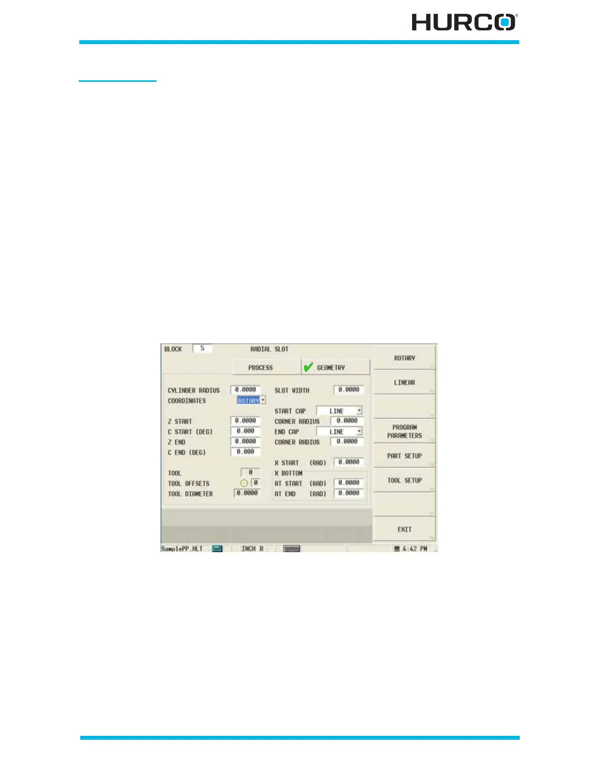
When Rotary is selected in the COORDINATES field, these fields appear:
Figure 2–87. Live-Tooling Radial Mill Radial Slot screen Geometry tab: Rotary Coordi-
nates
• Z START—defines the Z coordinate of the reference corner of the slot.
• C START (DEG)—defines the angle of the start point to the end point,
measured counterclockwise from the home position.
• Z END—defines the length of the slot along the Z axis.
• C END (DEG)—defines the length of the slot, in degrees, along the C axis,
measured counterclockwise from the home position.
 Loading...


