WinMax Lathe Conversational Part Programming v546CO Conversational Part Programming 2-49
Face Thread Type
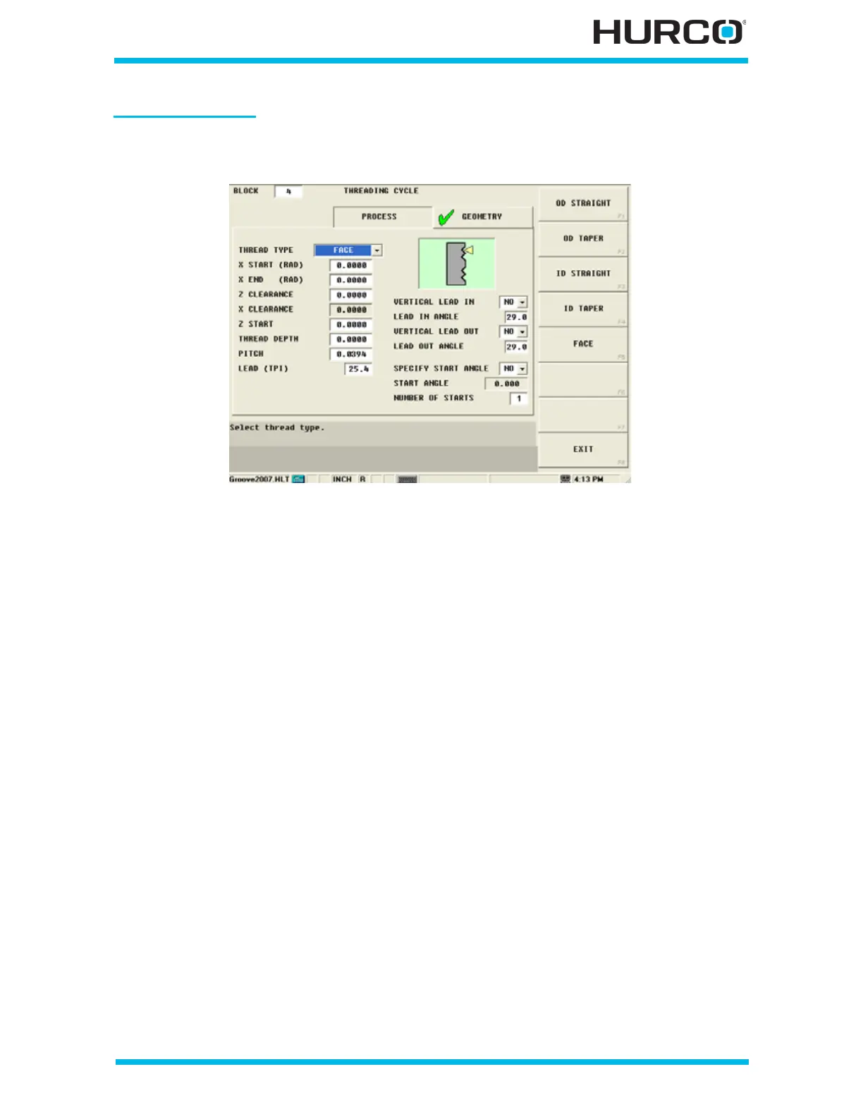
The following fields are available when face is selected in the Thread Type field:
Figure 2–39. Threading Cycle Geometry Tab Face Thread Type
• X START (DIA) or (RAD)—defines the X (DIA) or (RAD) startpoint for the
Threading cycle. The tool begins cutting at the programmed feedrate at this
location.
• X END (DIA) or (RAD)—identifies the X axis end location for the Threading
Cycle. The tool stops cutting at this location.
• Z CLEARANCE—identifies the distance that the tool should be moved away
from the part after the Threading cycle.
• X CLEARANCE—identifies the distance that the tool should be raised from
the part after the Threading cycle.
• Z START—identifies the Z axis starting location for the Threading cycle. The
tool begins cutting at the programmed feedrate at this location.
• THREAD DEPTH—identifies the incremental thread depth. The value must be
greater than 0.
• PITCH—defines the distance between threads for metric tools. Do not use
this field for programming tools measured in threads per inch.
• LEAD (TPI)—defines the threads per inch for tools measured in inches. Do
not use this field for programming metric tools.
• VERTICAL LEAD IN—defines whether the tool should enter the part
vertically (perpendicular) to the direction of the cut. Select YES or NO. NO is
the default. When YES is selected, the LEAD IN ANGLE field is inactive.
• LEAD IN ANGLE—defines the infeed angle that the tool follows in the X axis
to enter the workpiece. This angle is shown as 1 in the following figure; the
tool path is represented with a dotted line.
 Loading...


