WinMax Lathe Conversational Part Programming v546CO Conversational Part Programming 2-143
Blend Arc
From the New Axial Contour Segment screen, select Blend Arc F3, and the Axial Mill
Contour Blend Arc Segment screen appears with fields based on your choice in the
Coordinates field (Polar or Rectangular).
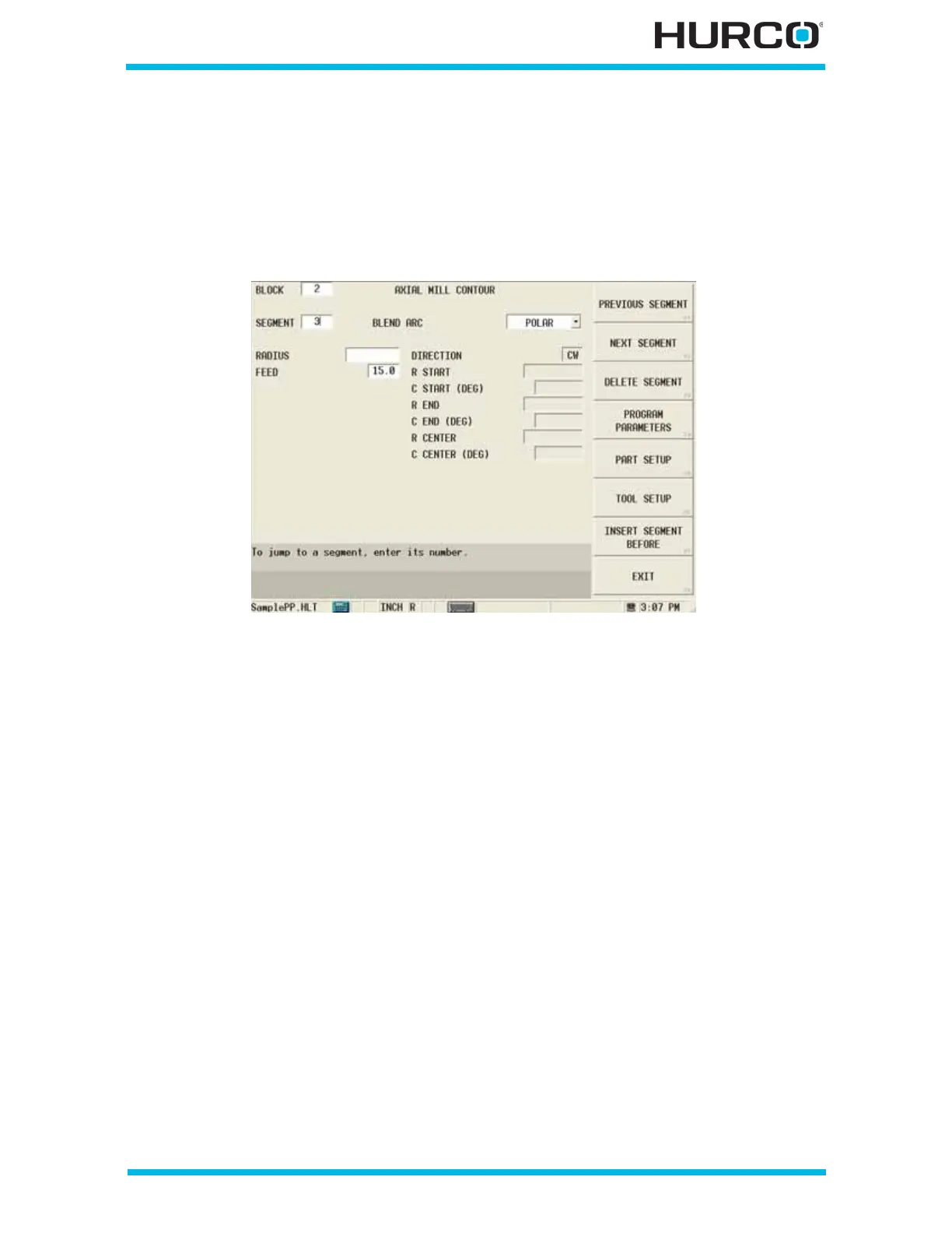
When Polar is selected in the COORDINATES field, these fields appear:
Figure 2–120. Live-Tooling Axial Mill Contour Blend Arc Segment screen: Polar Coordi-
nates
• RADIUS—defines the radius of the blend arc.
• FEED—contains the feed rate from the previous segment. This value can be
accepted or changed.
• DIRECTION—defines the direction, clockwise or counterclockwise, of the arc
from the start point. This read-only field is carried forward from a previous
arc segment and can only be edited in that screen.
• R START—contains the starting distance from the centerline. This read-only
field is carried forward from the previous segment and can only be edited in
that screen.
• C START (DEG)—contains the angle of the arc segment start point,
measured counterclockwise from the home position. This read-only field is
carried forward from the previous segment and can only be edited in that
screen.
• R END—contains the starting distance from the centerline. This read-only
field is carried forward from the previous segment and can only be edited in
that screen.
• C END (DEG)—defines the angle of the blend arc segment end point,
measured counterclockwise from the home position. This read-only field is
carried forward from the previous segment and can only be edited in that
screen.
 Loading...


