WinMax Lathe Conversational Part Programming v546CO Conversational Part Programming 2-51
Grooving Cycle
The Grooving cycle plunges out all extra material and then makes finish passes. The
width of the grooving tool must be programmed in Tool Setup. Grooves are simple shapes
with flat bottoms.
The turning center can cut inside, outside, and face grooves. Optional chamfer angles on
the corner of the groove may be programmed. You may also specify a different taper
angle for each wall. You may optionally specify each corner or fillet with a chamfer or
radius individually, i.e. one corner a chamfer, the other a radius.
Here are some examples:
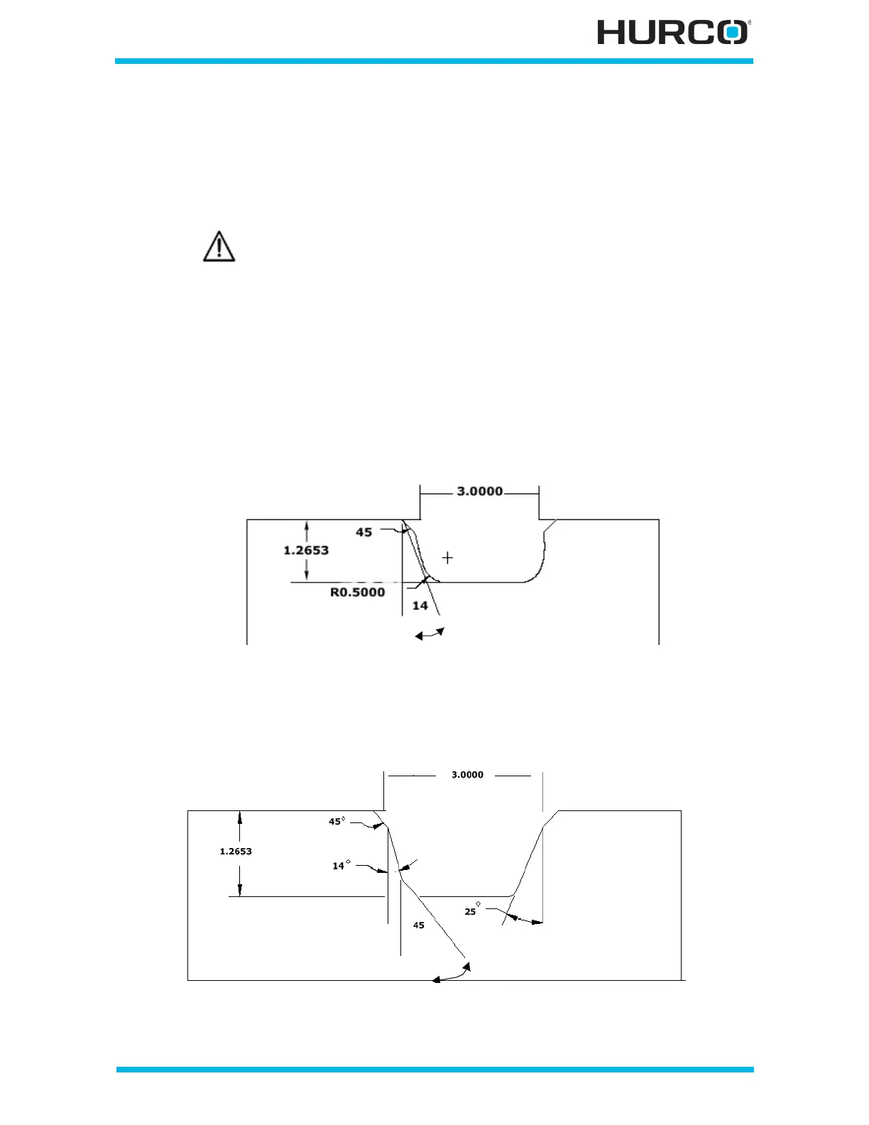
• Groove 45° chamfer at corners, 0.5 radius at fillets, left wall at 14° angle,
right wall no taper angle.
Figure 2–41. Groove Example 1
• Groove 45° chamfers at corners, 45° inside chamfer, 0.125 radius fillet, wall
at left 14°, wall at right 25°.
Figure 2–42. Groove Example 2
A Position block is required before a Groove data block if there is not
sufficient clearance for the tool to move around the part from a
previous data block.
 Loading...


