WinMax Lathe Conversational Part Programming v546CO Conversational Part Programming 2-101
• X BOTTOM (DIA) or (RAD)—defines the bottom of the hole and the location
where the Plunge Feed Rate ends.
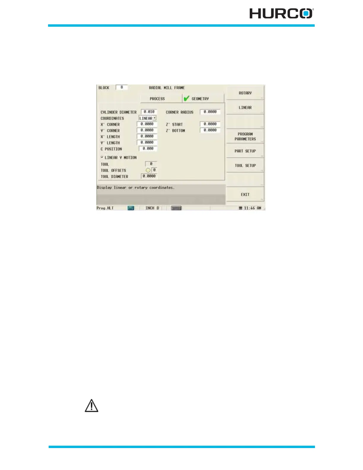
When Linear is selected in the COORDINATES field, these fields appear:
Figure 2–85. Live-Tooling Radial Mill Frame screen Geometry tab: Linear Coordinates
• X’ CORNER—defines the X Startpoint for the first segment of the contour.
The X’ axis will move in the physical Z direction.
• Y’ CORNER—defines the Y Startpoint for the first segment of the contour.
The Y’ axis will be wrapped on the cylinder diameter.
• X’ LENGTH—defines the X coordinate measured from the reference corner. If
the reference corner is at the left side of the rectangle, the X length is a
positive (+) dimension. If the reference corner is at the right side, the X
length is negative (-).
• Y’ LENGTH—defines the Y coordinate measured from the reference corner. Y
Length is positive (+) if the reference corner is at the lower left or lower right
of the rectangular area. Y Length is negative (-) if the reference corner is at
the top left or top right of the rectangle.
• C POSITION—defines the angle to position the C axis for the first segment
of the contour. This field appears when the Linear Y Motion checkbox is
selected. This field is available with TMX MY and TMX MYS series machines.
• LINEAR Y MOTION—select this checkbox to cause Y-Axis Motion using the X
and X’ axes. When this checkbox is clear, Y-Axis Motion occurs using the X
and C axes. Please refer to Programming Coordinates and Linear Y Motion, on
page 2 - 68 for examples. This field is available with TMX MY and TMX MYS
series machines.
Linear Y-Axis Motion is limited. The amount of Y travel is affected by
the X position and by any X-Axis tool length offset.
 Loading...


