2 - 156 Conversational Part Programming v546CO WinMax Lathe Conversational Part Programming
• BLEND OFFSET—identifies the XY distance from the entry point of the part
surface and the Z plunge point where the tool enters the work piece. This
move is always a 90° arc and occurs at the 6:00 position on the frame. This
parameter is used for the blend-in move in milling and for the blend-out
move from the part surface to the Z Retract point. The default value is 3.000
mm (0.1250 inches). This field is available when either Inside, Outside, or
Pocket Boundary is selected for the Milling Type.
• BLEND OVERLAP—identifies the distance the tool travels past the entry
point before exiting from the part. The default value is 3.000 mm (0.1250
inches). This field is available when either Inside, Outside, or Pocket
Boundary is selected for the Milling Type.
• DIRECTION—identifies the milling direction as either Conventional or Climb.
This field is not available when On is selected for the Milling Type. Refer to
Cutter Compensation, on page 2 - 188 for details about milling direction.
• PECK DEPTH—identifies the maximum depth to be cut in one pass. This field
is not available when Finish Only is selected for the Strategy.
• 1ST PECK OFFSET—identifies the depth of the first peck when it needs to be
different than subsequent pecks, identified in Peck Depth. This field is not
available when Finish Only is selected for the Strategy.
• PECK CLEARANCE—identifies the distance above the previous peck level to
which the Z axis returns at rapid traverse. This field is not available when
Finish Only is selected for the Strategy.
• CUTTER COMP—identifies the type of milling to insert between segment
end points. Choose between Arc or Lines. This field is not available when
On is selected for the Milling Type. If Arc is selected, a tangent arc is
inserted to connect two line segments, or a line segment and an arc
segment (when the two cutter compensated segments are offset and do
not intersect). When using the Arc method, the system creates the cutter
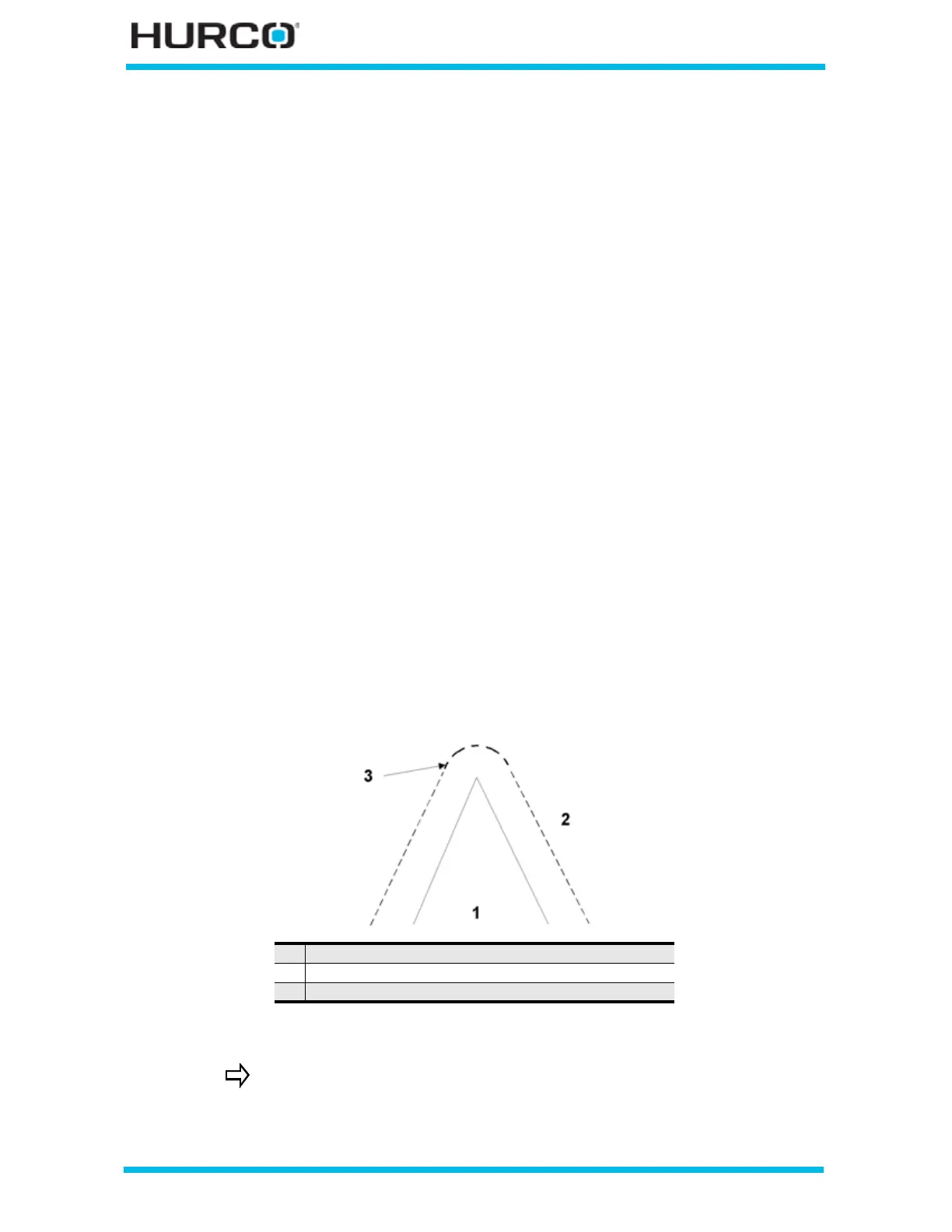
compensated path as shown below:
Figure 2–128. Cutter Compensation Using the Arc Parameter
1 Programmed tool path
2 Cutter compensated path
3 Arc parameter
Some operators find the Arc method inappropriate for their
applications because the cutter remains in contact with the work
piece and may drag a chip across a sharp angle on the part. In such
circumstances, operators select Lines.
 Loading...


