190 Keysight N9038A MXE Service Guide
RF Preselector Section
RF Preselector Section Troubleshooting
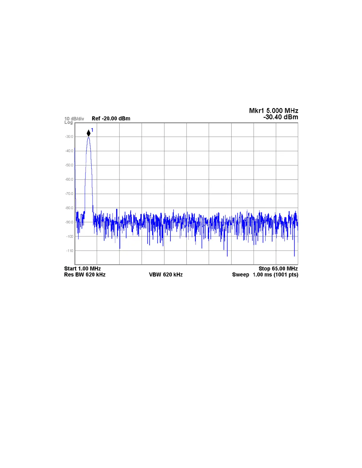
9. Verify that the signal level on the spectrum analyzer is greater than
−35 dBm, as shown in Figure 5-17, allowing for any additional test cable
loss.
If the signal level is incorrect the most likely cause of the problem is the
A21 RF Preselector Input assembly itself.
Figure 5-17 A21 RF Preselector Input Assembly - DDS Output
10.Vary the frequency of the Direct Digital Synthesizer alignment signal
across its frequency range and verify that the signal level remains greater
than −35 dBm up to 40 MHz. Above 40 MHz the signal level should remain
greater than −40 dBm.
Broad Band Noise Source - Radiated Band
11.Move the spectrum analyzer to the A21 RF Preselector Input assembly
Radiated Band Pre-Filtered Output (J102), as shown in Figure 5-4.
12.Tune the spectrum analyzer to a start frequency of 10 MHz and a stop
frequency of 4 GHz.
13.Tune the instrument to a frequency of 100 MHz with a span of 0 Hz by
pressing FREQ, 100 MHz, and SPAN, Zero Span.

 Loading...


