Keysight N9038A MXE Service Guide 299
Front End Control
A15 Front End Control Assembly Troubleshooting
11.If the level is not correct, measure the input signal level coming to A15
J902 out of W14, as shown in Figure 8-6. It should be at approximately the
same level shown in Figure 8-14.
If the input signal is at the correct level, and the output is not, the A15
Enhanced Front End Control Assembly has a problem.
If the input signal is not at the correct level see Chapter 6, “RF
Downconverter Section.” for instructions on how to determine the cause
of this problem.
12.Reconnect W16 to A15J 900 as shown in Figure 8-6.
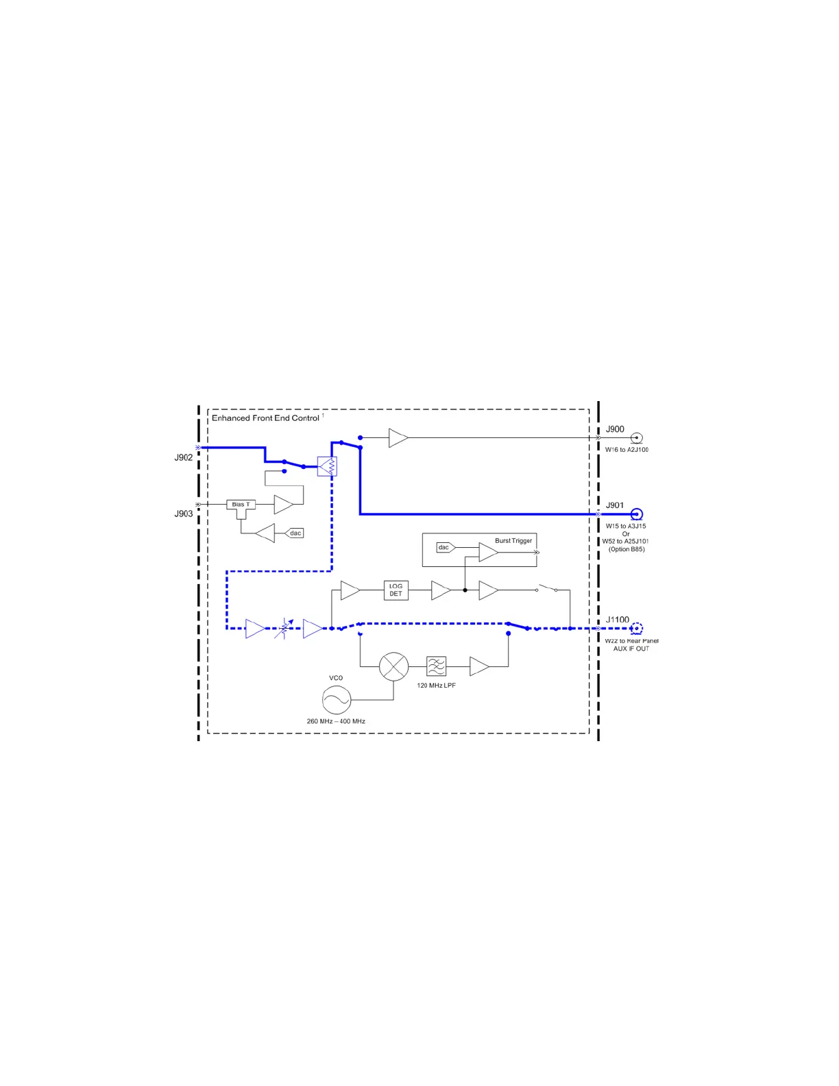
The 300 MHz IF signal routing for the A25 Wideband Analog IF output of
the A15 Enhanced Front End Control board can be seen in the solid heavy
blue line in Figure 8-15.
Figure 8-15 300 MHz IF Switching to A25 Wideband Analog IF

 Loading...


