AKD Installation | 8 Electrical Installation
8.10 Motor Connection
Together with the motor supply cable and motor winding, the power output of the drive forms
an oscillating circuit. Characteristics such as cable capacity, cable length, motor inductance,
and frequency (➜ p. 34 or ➜ p. 35) determine the maximum voltage in the system.
The dynamic voltage rise can lead to a reduction in the motor operating life and, on unsuitable
motors, to flashovers in the motor winding.
l Only install motors with insulation class F (acc. to IEC60085) or above.
l Only install cables that meet the requirements ➜ p. 39.
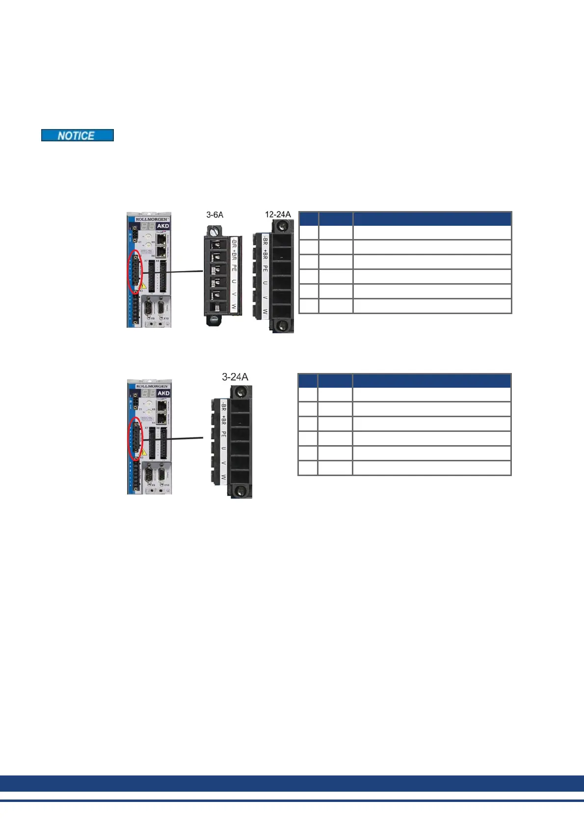
Connector X2 AKD-xzzz06
Pin Signal Description
1 -BR Motor holding brake, negative
2 +BR Motor holding brake, positive
3 PE Protective earth (motor housing)
4 U Motor phase U
5 V Motor phase V
6 W Motor phase W
Connector X2 AKD-xzzz07
Pin Signal Description
1 -BR Motor holding brake, negative
2 +BR Motor holding brake, positive
3 PE Protective earth (motor housing)
4 U Motor phase U
5 V Motor phase V
6 W Motor phase W
100 Kollmorgen™ | May 2013

 Loading...


