AKD Installation | 8 Electrical Installation
8.11.10 Incremental Encoder
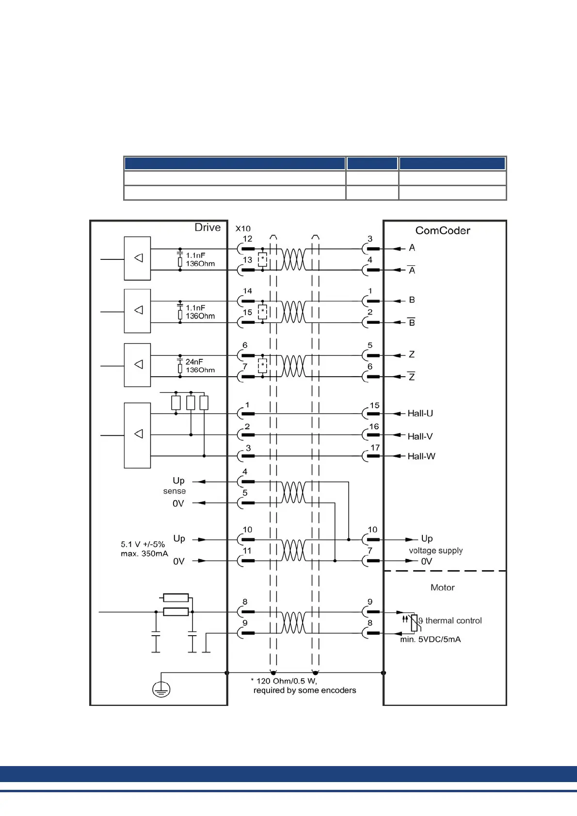
Feedback devices, which do not deliver absolute information for commutation, can either
work with wake&shake commutation (see AKD User Guide) or can be used as a complete
feedback system when combined with an additional Hall encoder. All signals are connected
using a pre-assembled comcoder connection cable. The thermal control in the motor is con-
nected via the encoder cable and evaluated in the drive.
If cable lengths of more than 25 m are planned, please consult customer support.
Type FBTYPE Frequency Limit
Incremental Encoder&Hall Switches (Comcoder) 10 2.5 MHz
Incremental Encoder (Wake&Shake) 11 2.5 MHz
The pin assignment shown on the encoder side relates to Kollmorgen™ motors.
114 Kollmorgen™ | May 2013

 Loading...


