AKD Installation | 8 Electrical Installation
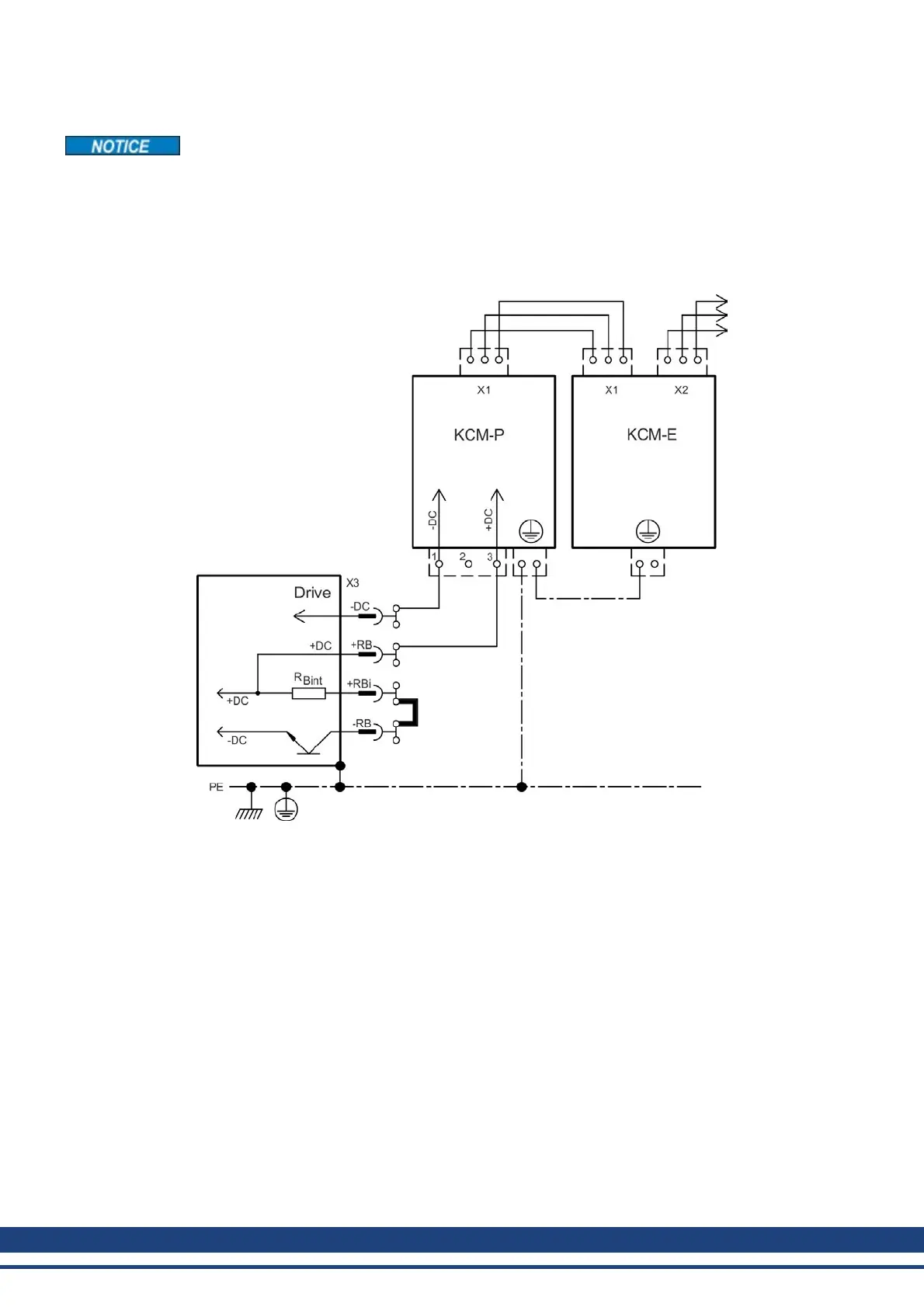
8.9.2.3 Example installation with KCM-P and KCM-E
Maximum cable length between AKD and KCM: 500mm. The DC+ and DC- lines should
always be twisted, maximum cross section is 6mm². Ensure that the polarity is correct,
swapping round DC+/DC- will damage the KCM modules.
The KCM-P starts the charging process at approx. 470 V DC. If the power supply fails, the
module provides the DC bus link with the stored energy (this only applies to the power supply
voltage; battery-back the 24 V supply separately).
Setup KCM-P and KCM-E
Prerequisite for the following instructions:
l Properly disconnected, grounded system.
l KCM-P: assembled and wired in the switching cabinet. Set AKDundervoltage limit
VBUS.UVTHRESH to a value significantly below 470V DC, otherwise AKD will switch-
off before KCM-P provides energy to the DC bus link.
l KCM-E: assembled and connected to the KCM-P with connection cable (X1) and PE line.
l Discharge aids (plug-in bridge) are removed.
Proceed as instructed below:
1. Switch on the line voltage.
2. The KCM-P begins the charging process at approx. 470 V DC; the LED flashes.
98 Kollmorgen™ | May 2013

 Loading...


