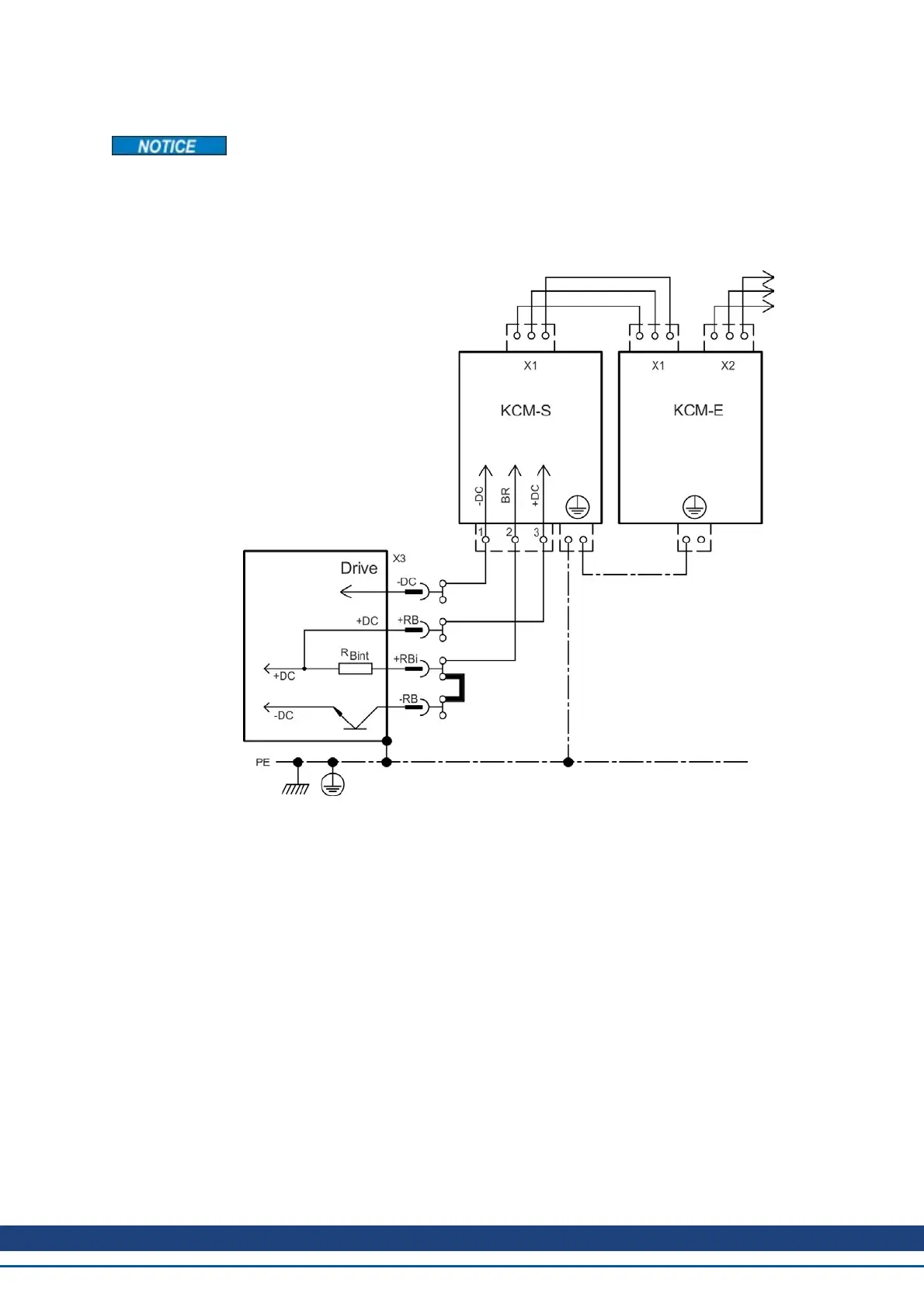
8.9.2.2 Example installation with KCM-S and KCM-E
Maximum cable length between AKD and KCM: 500mm. The DC+ and DC- lines should
always be twisted, maximum cross section is 6mm². Ensure that the polarity is correct,
swapping round DC+/DC- will damage the KCM modules.
Connect the BR connection to theAKD with the most frequent generative braking processes
in the system. This AKD must have an active internal or external brake resistor. Create a
motion profile that causes the brake chopper to respond.
Setup KCM-S and KCM-E
Prerequisite for the following instructions:
l Properly disconnected, grounded system.
l KCM-S: assembled and wired in the switching cabinet. The load that leads to the acti-
vation of the brake chopper during braking must be connected.
l KCM-E: assembled and connected to the KCM-S with connection cable (X1) and PE line.
l Discharge aids (plug-in bridge) are removed.
Proceed as instructed below:
1. Switch on the line voltage.
2. Enable the AKD and operate the motion profile that causes the brake chopper to respond.
3. The KCM-S determines the chopper threshold and begins to charge; LED (top view)
flashes. The energy stored in the capacitor module during generative braking is available
the next time acceleration happens.
AKD Installation | 8 Electrical Installation
Kollmorgen™ | May 2013 97

 Loading...


