AKD Installation | 8 Electrical Installation
8.11.8 Sine Encoder with Hiperface
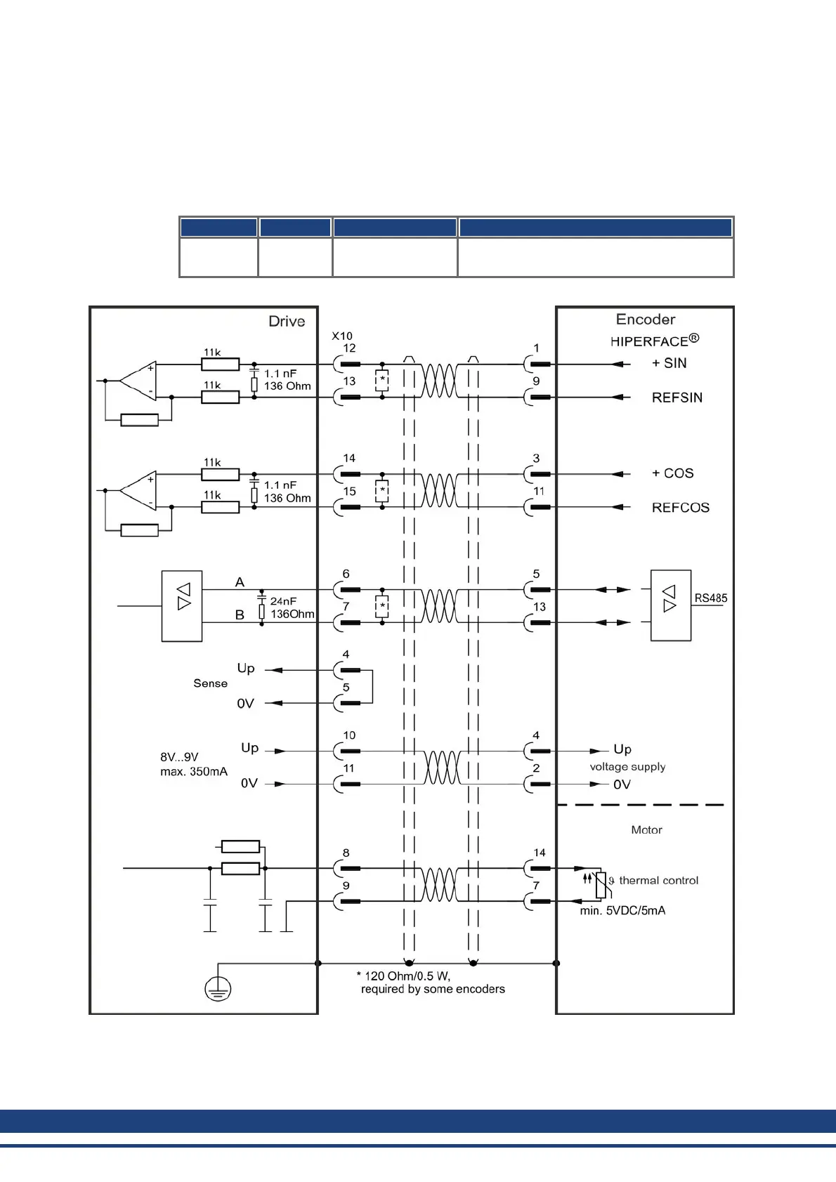
The diagram below shows the wiring of a single-turn or multi-turn sine-cosine encoder with
Hiperface interface as a feedback system.
The thermal control in the motor is connected via the encoder cable and evaluated in the
drive. All signals are connected using our pre-assembled encoder connection cable.
If cable lengths of more than 50 m are planned, please consult customer support.
Type FBTYPE Frequency Limit Description
Hiperface 33 1 MHz Connecting pin 4 and 5 together causes Up
to be 8 to 9 V
The pin assignment shown on the encoder side relates to Kollmorgen™ motors.
112 Kollmorgen™ | May 2013

 Loading...


