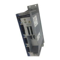
AKD Installation | 6 Technical description and data
6.1 The AKD Family of Digital Drives
Available AKD versions
Variant (short) Description Current Housing Connectivity
AKD-B*** Base drive is controlled by
analog torque & velocity com-
mands (electronic gearing).
3 to 24 A Standard Analog, SynqNet
AKD-P** Position Indexer drive adds the
ability to command multiple
motions, process I/O, make
decisions, add time delays,
and modify drive process var-
iables to the base drive.
3 to 24 A Standard Analog, CANopen,
EtherCAT, PRO-
FINET RT, Eth-
ernet/IP
AKD-M***-MC Motion Controller PDMM/Ether-
CAT master drive. Includes all
five IEC 61131 languages,
PLC Open and Pipes Network.
This drive is called AKD
PDMM.
3 to 12 A Extended
width
EtherCAT
AKD-T*** Simple BASIC pro-
grammability added to the to
the Base drive. This drive is
called AKD BASIC.
3 to 24 A Standard Analog, PROFINET
RT, Ethernet/IP
AKD-T***-IC AKD BASIC with I/O expan-
sion.
3 to 24 A Extended
width
Analog, I/O expan-
sion
Standard features
l Supply voltage range 120 V to 480 V ±10%
l Several housing dimensions, depending on current and hardware options.
l Motion bus onboard.
l TCP/IP service channel onboard.
l SFD, Hiperface DSL, Tamagawa Smart Abs, Resolver, Comcoder, 1Vp-p Sin-Cos
encoders, incremental encoders support onboard.
l Support for ENDAT 2.1 & 2.2, BiSS or HIPERFACE protocols onboard.
l Encoder emulation onboard.
l Second feedback support.
l Safe Torque Off (STO) according to IEC 61508 SIL 2 onboard.
l Use with Synchronous servomotors, linear motors, and induction machines can be used.
Power section
l One or three phase supply, voltage range 120 to 480 V ±10%, 50 to 400 Hz ±5% or DC.
l Connection to higher voltage mains only via isolating transformer, ➜ p. 90
l B6 bridge rectifier, integral soft-start circuit.
l Single phase supply possible with output power derating.
l Fusing to be provided by the user.
l Shielding star point close to the drive.
l DC bus link voltage range 170 to 680 Vdc, can be connected in parallel.
l Output stage IGBT module with floating current measurement.
l Regen circuit with dynamic distribution of the generated power between several drives on
the same DC bus link circuit.
l Internal regen resistor for all 240/480 Vac AKD-xzzz07 models (only 120/240 Vac 3 A and
6 A AKD-xzzz06 models lack internal regen resistors), external regen resistors if required.
30 Kollmorgen™ | May 2013

 Loading...