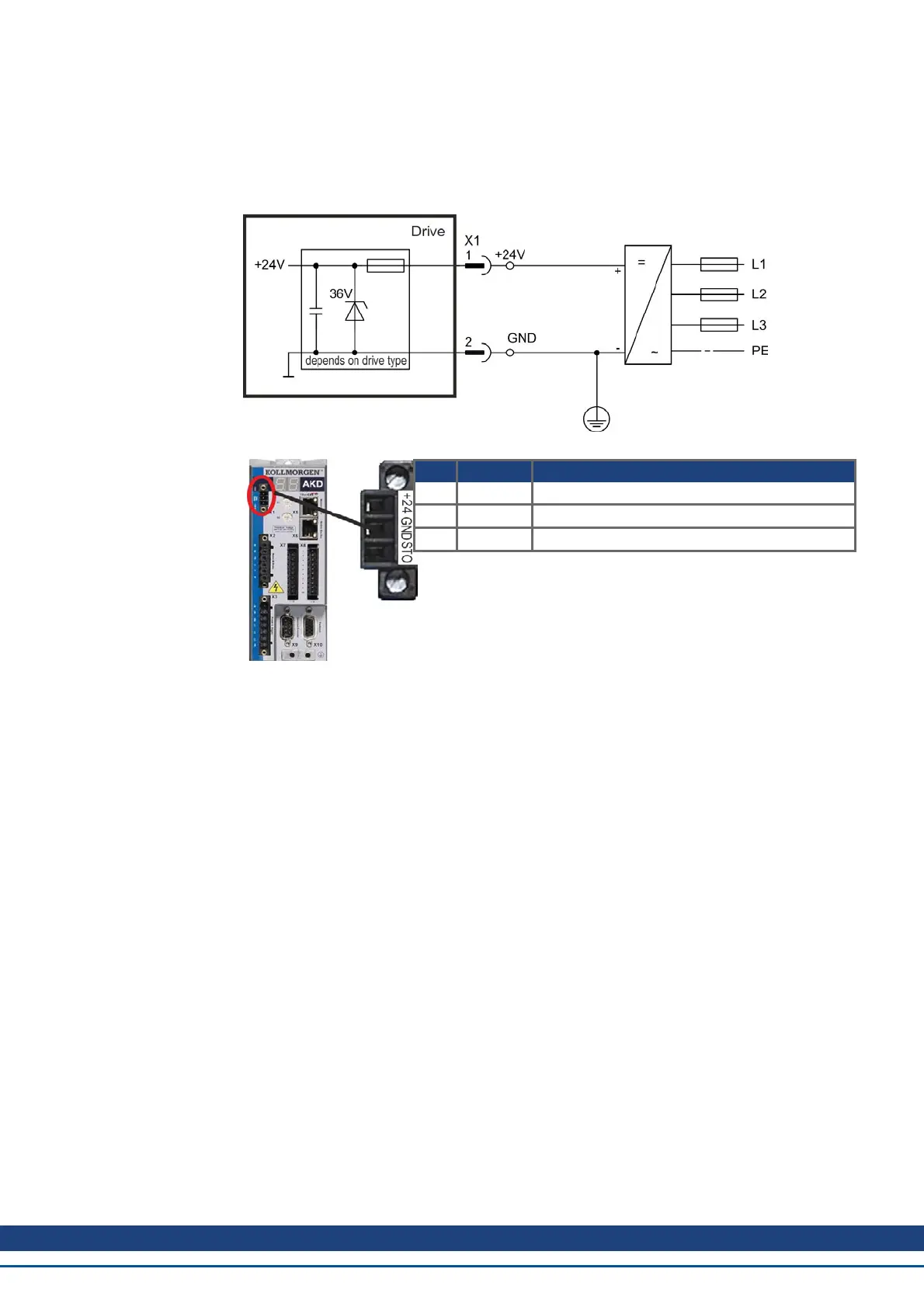
8.8.3 24 V Auxiliary Supply (X1)
The following diagram describes external 24 Vdc power supply, electrically isolated, for
example, via an isolating transformer. The required current rating depends on the use of
motor brake and option card ➜ p. 34 or ➜ p. 35).
Pin Signal Description
1 +24 +24 Vdc Auxiliary voltage
2 GND 24V Supply GND
3 STO STO enable (Safe Torque Off)
AKD Installation | 8 Electrical Installation
Kollmorgen™ | May 2013 91
 Loading...


