3-2 831 Components Model 831 Manual
• AC/DC output, control, USB, and external power
connectors (shown in FIGURE 3-2)
• True “hand held” instrument with “sure grip” pads
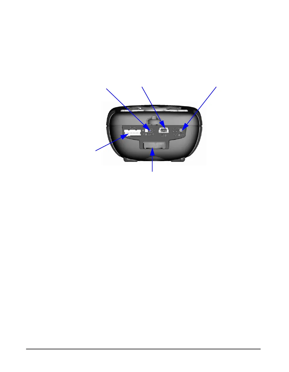
FIGURE 3-2 shows the bottom view of the Model 831.
FIGURE 3-2 Model 831 Bottom View
DO NOT use the hardware power
switch to turn the Model 831 ON or
OFF. This will cause data to be lost.
The purpose of this switch is to
disconnect the batteries for storage
(1 to 2 weeks). It is recommended
that the batteries be removed from
the instrument if it will not be used
for a month or longer (the batteries
may self-discharge and leak,
damaging the instrument).
• Hardware Power Switch: When set to “O”, completely
powers down the Model 831 for storage. However, the
real-time clock will maintain its value for six minutes,
long enough to complete a battery change. Set to “|” for
instrument operation.
• USB Interface: USB 2.0 peripheral full-speed port used
for communication with a PC, control of the Model 831
from the PC and downloading of data from the Model
831 to the PC. The PSA029 external power supply may
be connected here. The maximum USB cable length is 5
m and the cable is part number CBL138.
• AC/DC Output and Headset Jack: used to output
analog AC and DC signals or to connect to a headset for
the recording and playback of voice records.
• AUX Connector for USB: intended for use with USB
mass storage, cellular & dial-up modems, GPS and
future devices.
Hardware Power Switch
USB Interface
AC/DC Output and Headset
I/O Connector for 831-INT, External
Power, Analog and Logic I/O.
AUX Connector
for USB