11 System bus "CAN on board"
11.3 LED status displays for the system bus
706
Lenze · 8400 HighLine · Reference manual · DMS 12.0 EN · 06/2017 · TD23
_ _ _ _ _ _ _ _ _ _ _ _ _ _ _ _ _ _ _ _ _ _ _ _ _ _ _ _ _ _ _ _ _ _ _ _ _ _ _ _ _ _ _ _ _ _ _ _ _ _ _ _ _ _ _ _ _ _ _ _ _ _ _ _
Example: Setting of the node address 23
11.3 LED status displays for the system bus
Inverter is not (yet) active on the system bus
Inverter is active on the system bus
• LED "CAN-RUN" signals the CANopen state:
• LED "CAN-ERR" signals a CANopen error:
DIP switch 64 32 16 8 4 2 1
Switch position OFF OFF ON OFF ON ON ON
Value 0 0
16 0 4 2 1
Node address = Sum of the values = 16 + 4 + 2 + 1 = 23
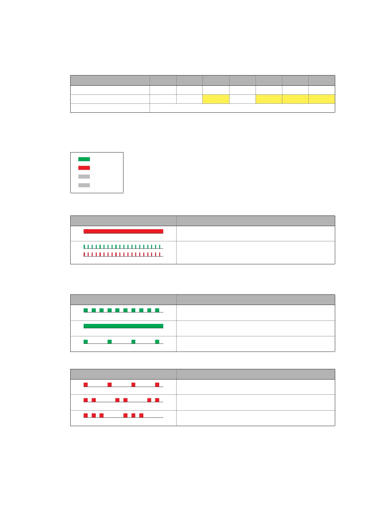
Information about the status of the system bus can be obtained quickly via
LED displays "CAN-RUN" and "CAN-ERR" on the front of the inverter.
The meaning can be seen from the tables below.
LED display Meaning
(CAN-ERR is permanently lit)
Inverter is not active on the system bus / Bus Off
(CAN-RUN and CAN-ERR flicker)
Automatic detection of baud rate is active
LED display CANopen state
(CAN-RUN is blinking every 0.2 seconds)
Pre-Operational
(CAN-RUN is permanently lit)
Operational
(CAN-RUN is blinking every second)
Stopped
LED display CANopen error
(CAN-ERR is blinking once, then off for 1 second)
Warning Limit reached
(CAN-ERR is blinking twice, then off for 1 second)
Node Guard Event
(CAN-ERR is blinking three times, then off for 1 second)
Sync Message Error
(only possible in the "Operational" state)
CAN-RUN
CAN-ERR
DRV-RDY
DRV-ERR