Lenze · 8400 HighLine · Reference manual · DMS 12.0 EN · 06/2017 · TD23 59
3 Commissioning
3.7 Commissioning of the "Actuating drive speed" technology application
_ _ _ _ _ _ _ _ _ _ _ _ _ _ _ _ _ _ _ _ _ _ _ _ _ _ _ _ _ _ _ _ _ _ _ _ _ _ _ _ _ _ _ _ _ _ _ _ _ _ _ _ _ _ _ _ _ _ _ _ _ _ _ _
3.7.1 Prepare inverter for commissioning
1. Power terminal wiring.
Refer to the mounting instructions supplied with the inverter to find help on how to correctly
design the power connections to match the requirements of your device.
2. Wire the control terminals.
The assignment for your digital inputs should correspond to one of the preconfigured control
modes (C00007
) for terminal control:
3. Inhibit inverter: Set terminal X5/RFR to LOW level or open contact.
4. Connect USB diagnostic adapter.
5. Switch on voltage supply of the inverter.
• Without motor operation
: Connect external 24 V supply.
•With motor operation
: Connect mains voltage.
If the green "DRV-RDY" LED is blinking and the red "DRV-ERR" LED is off, the inverter is ready for
operation and commissioning can proceed.
Related topics:
Automatic restart after mains connection/fault...
( 123)
LED status displays
( 624)
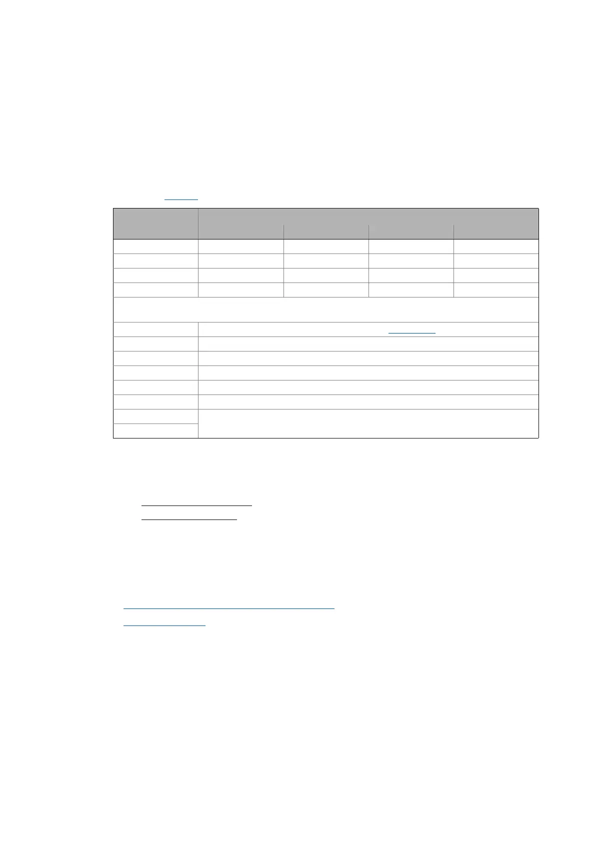
Assignment of the digital terminals
Control mode DI1 DI2 DI3 DI4
Terminals 0 JOG 1/3 JOG 2/3 DCB Cw/Ccw
Terminals 2 JOG 1/3 JOG 2/3 QSP Cw/Ccw
Terminals 11 Cw/Ccw DCB MPotUp MPotDown
Terminal 16 JOG 1/3 JOG 2/3 Cw/QSP Ccw/QSP
Abbreviations used:
JOG Selection of fixed setpoints 1 ... 3 parameterised in C00039/1...3
DCB Manual DC-injection braking
Cw/Ccw CW/CCW rotation
QSP Quick stop
MPotUp Motor potentiometer: Increase speed
MPotDown Motor potentiometer: Reduce speed
Cw/QSP Fail-safe selection of the direction of rotation in connection with quick stop
Ccw/QSP