17 Function library
17.1 Function blocks | L_MFail_1
1407
Lenze · 8400 HighLine · Reference manual · DMS 12.0 EN · 06/2017 · TD23
_ _ _ _ _ _ _ _ _ _ _ _ _ _ _ _ _ _ _ _ _ _ _ _ _ _ _ _ _ _ _ _ _ _ _ _ _ _ _ _ _ _ _ _ _ _ _ _ _ _ _ _ _ _ _ _ _ _ _ _ _ _ _ _
17.1.102.1 Procedure of the mains failure control
A failure of the voltage supply of the power section can be detected by
• an evaluation of the DC-bus voltage
and/or
• an external monitoring system (e.g. voltage measuring relay).
The type of mains failure control to be used depends on the used drive system.
Evaluation of the DC-bus voltage
This proceeding is used for single drives or multi-axis drives which do not use an external
monitoring system.
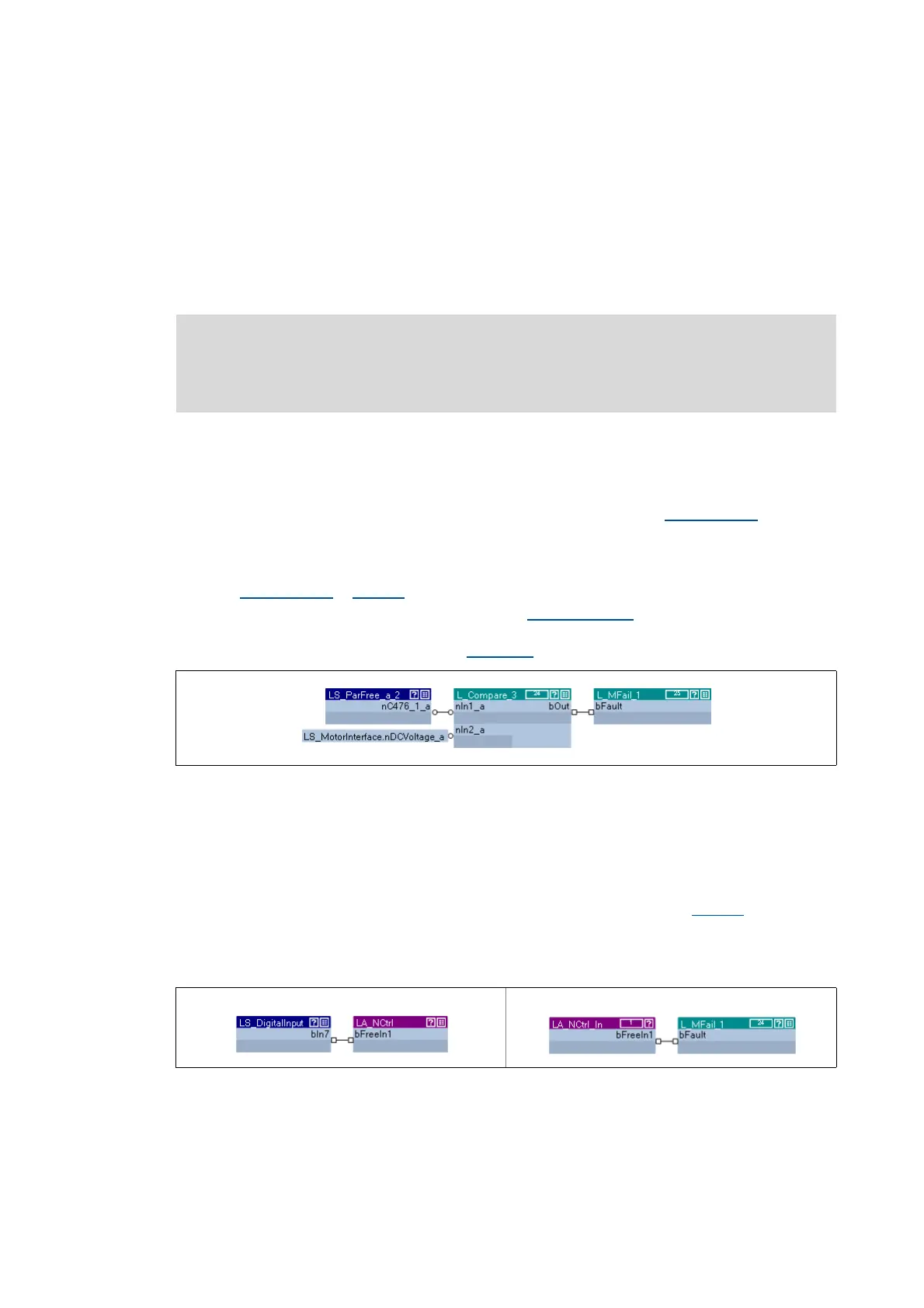
• For evaluating the DC-bus voltage, you can use a comparator (e.g. FB L_Compare_3
) as shown
in the following interconnection example 1.
• In order that the mains failure control will be activated if the DC-bus voltage falls below a
certain operating threshold, set the comparison function "2: In1 > In2" has to be set for the
FB L_Compare_3
in C00690.
• For specifying the operating threshold, the SB LS_ParFree_a_2
is used. This system block can
output 16 parameterisable analog signals. In the shown example, the operating threshold
has to be set in the "free parameter" C00476/1
.
[17-43] Interconnection example 1: Evaluation of the DC-bus voltage with a comparator (cutout)
Use of an external monitoring system
In this proceeding, the digital status signal of an external monitoring system is connected to the
FB L_MFail_1 via a digital input of the inverter.
• In the following example, the digital input DI7 is used.
• The active level (HIGH or LOW active) for DI7 has to be parameterised in C00114
in such a way
that bFault becomes TRUE when the monitoring system is tripped.
• A free input of the application block can be used to transfer the digital input signal from I/O
level to application level.
[17-44] Interconnection example 2: Use of the digital status signal of an external monitoring system
Note!
The following interconnection examples are not functional yet. For an error-free
function, connect the FB L_MFail_1 with further signals!
IO level: Application level: