5 Motor control (MCTRL)
5.9 Servo control (SC)
248
Lenze · 8400 HighLine · Reference manual · DMS 12.0 EN · 06/2017 · TD23
_ _ _ _ _ _ _ _ _ _ _ _ _ _ _ _ _ _ _ _ _ _ _ _ _ _ _ _ _ _ _ _ _ _ _ _ _ _ _ _ _ _ _ _ _ _ _ _ _ _ _ _ _ _ _ _ _ _ _ _ _ _ _ _
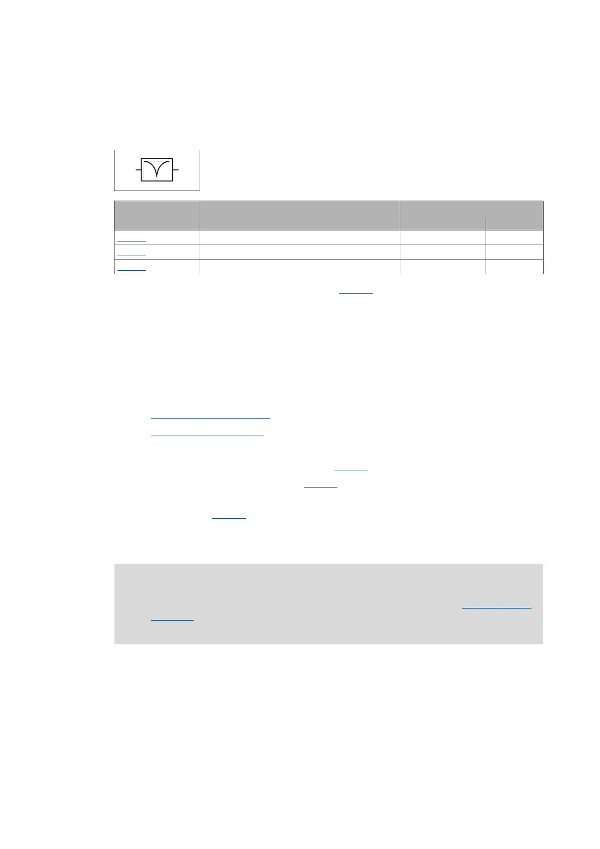
5.9.4.4 Setting the current setpoint filter (band-stop filter)
Due to the high dynamic performance/limit frequency of the closed current control loop,
mechanical natural frequencies can be activated which may lead to an unstable speed control loop.
• In the default setting of 0 db of the filter depth (C00272
), the current setpoint filter is switched
off.
Setting of the current setpoint filter
Since the frequency response of the speed controlled system is only rarely known to such an extent
that the current setpoint filter can be adjusted to the controlled system in the run-up, the following
example describes how to set the current setpoint filter.
How to set the current setpoint filter:
1. Optimise current controller
( 241).
2. Optimise speed controller
( 242)
3. Measure the oscillation frequency (observe current or speed).
4. Set the measured oscillation frequency in C00270
as filter frequency.
5. Set "25%" of the filter frequency in C00271
as filter width.
• Example: Filter frequency = 200 Hz filter width = 50 Hz.
6. Set "40 dB" in C00272
as filter depth.
• If the filter depth is set to "0 dB" (default setting), the filter is not active.
To mask out or at least damp these resonant frequencies, a so-called current
setpoint filter is integrated into the speed control loop of the inverter.
Parameters Info Lenze setting
Value Unit
C00270 SC: Freq. current setpoint filter 200.0 Hz
C00271
SC: Current setpoint filter width 0.0 Hz
C00272
SC: Current setpoint filter depth 0 dB
Note!
Readjust the speed controller after setting the current setpoint filter. Optimise speed
controller. ( 242)
The setting of the current setpoint filter reduces the available maximum drive torque.