4 Device control (DCTRL)
4.2 Device state machine and device states
114
Lenze · 8400 HighLine · Reference manual · DMS 12.0 EN · 06/2017 · TD23
_ _ _ _ _ _ _ _ _ _ _ _ _ _ _ _ _ _ _ _ _ _ _ _ _ _ _ _ _ _ _ _ _ _ _ _ _ _ _ _ _ _ _ _ _ _ _ _ _ _ _ _ _ _ _ _ _ _ _ _ _ _ _ _
4.2.2 Init
The inverter is in this status immediately after switching on its 24 V supply voltage.
In the "Init" status, the operating system is initialised and all device components (communication
module, memory module, power section, etc.) are identified. When identifying the power section, it
is checked first if it is switched on or if the required voltage lies within the tolerance zone,
respectively.
• The inverter is inhibited, i.e. the motor terminals (U, V, W) of the inverter are deenergised.
• The digital and analog inputs are not yet evaluated at this time.
• The bus systems (CAN, PROFIBUS etc.) do not work yet, i.e. communication is not possible.
• The application is not yet processed.
• The monitoring functions are not active yet.
• The inverter cannot be parameterised yet and no device commands can be carried out yet.
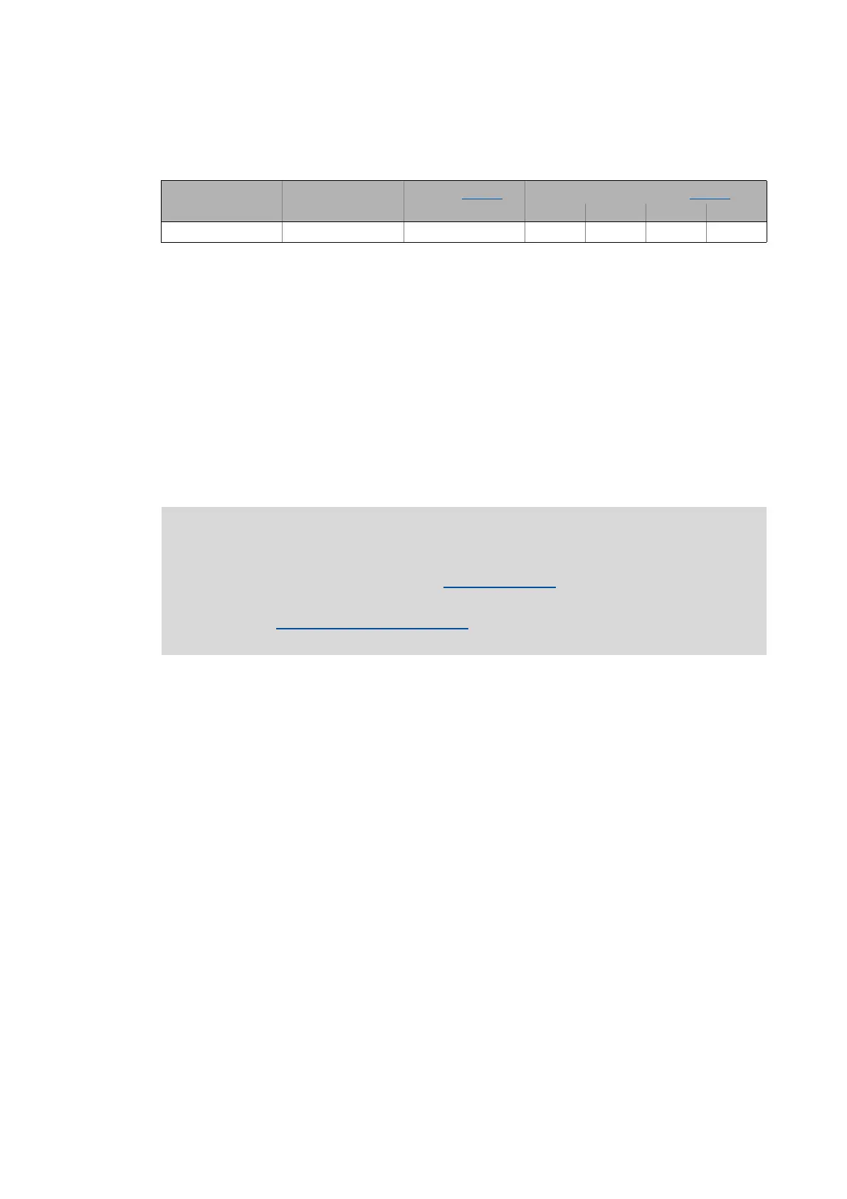
"DRV-RDY" LED LED "DRV-ERR" Display in C00137 Display in status word 1 (C00150)
Bit 11 Bit 10 Bit 9 Bit 8
OFF OFFInit 0001
Note!
If the 24V voltage supply is in the valid range (>19V) and the initialisation is finished, the
device changes automatically to the "ReadyToSwitchOn
" status.
If only the 24V voltage supply is available during the mains connection, the error
message "LU: Undervoltage in the DC bus
" is also entered into the logbook of the
inverter.