Operating elements for crane operation
9.2 Short description of the operating elements
Operating manual 3 302 736 en 9 - 133
GMK4090
xx.xx.xxxx
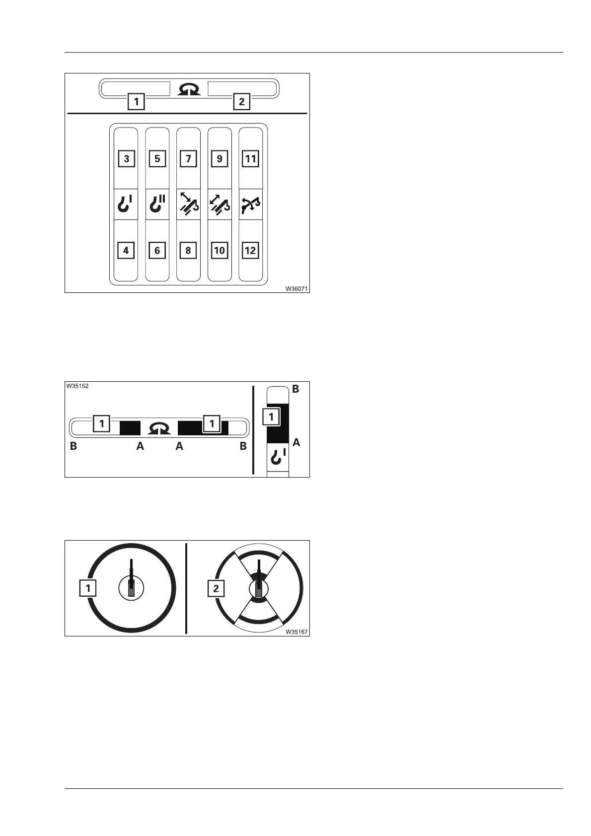
Maximum permissible speed display
Separate displays are provided for each
direction of movement.
A bar (1) shows the maximum permissible
speed – scale from 0% (A) to 100% (B).
The colour of the bar (1) changes.
à On the CCSdisplay, p. 11 - 51
Slewing range display
The function is identical to the display in the
Lifting capacity table menu.
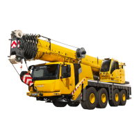
s
1 Slewing to the left
2 Slewing to the right
3 Lower the main hoist
4 Lift the main hoist
5 Lower the auxiliary hoist
6 Lifting the auxiliary hoist
7 Lowering the boom
8 Raising
9 Extension
10 Retraction of the telescoping
11 Lower the lattice extension
12 Raise the lattice extension
Red: 0% to 10%
Yellow: 11% to 25%
Green: 26% to 100%
1 For the Standard slewing range type;
à p. 11 - 58
2 For the
MAXbase slewing range type;
à p. 11 - 60
 Loading...