Ignition
Page 2A-24 90-8M0050731 MAY 2011
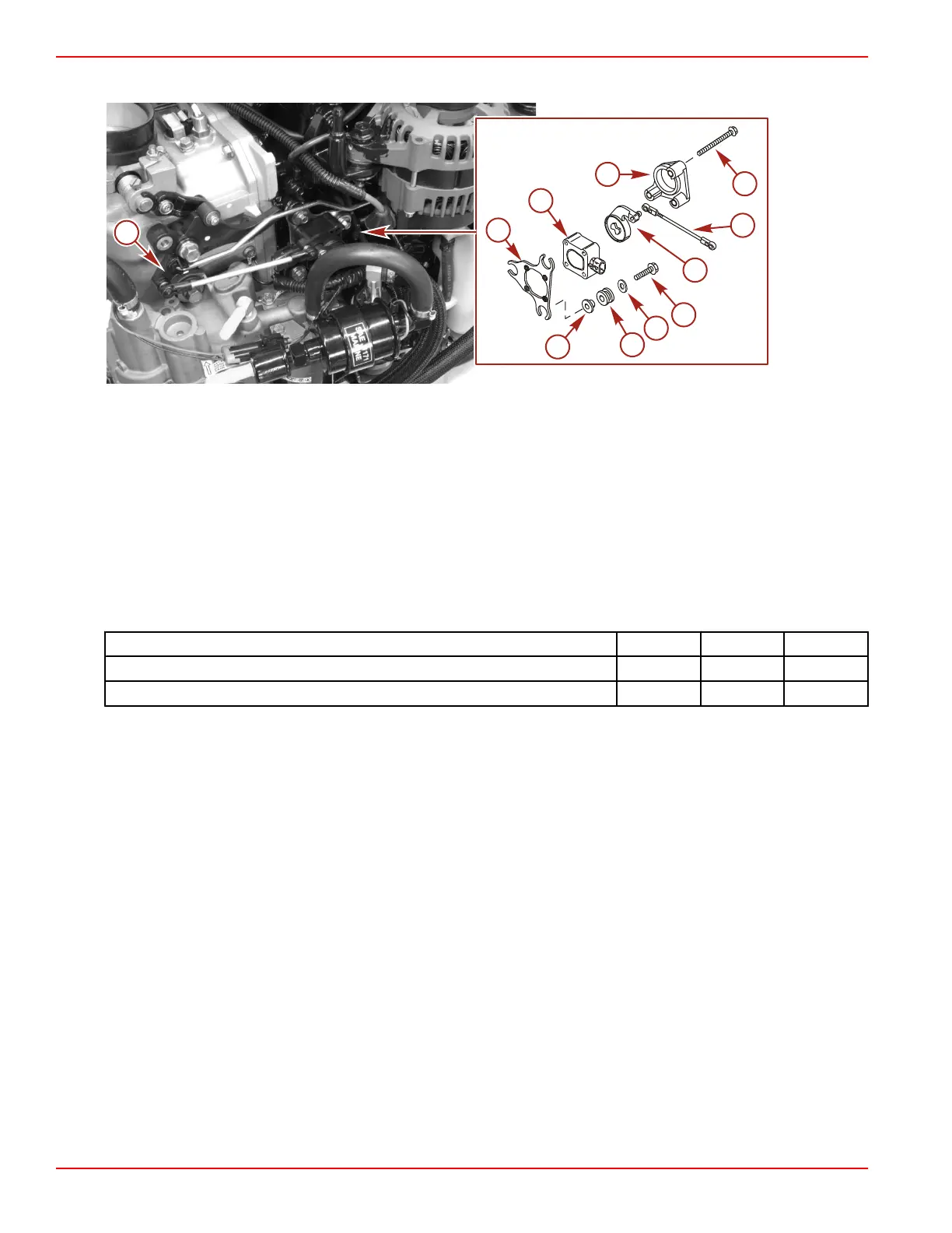
2. Install the TPS link arm assembly onto the TPS lever. Verify the TPS lever is engaged with the TPS.
a - Sensor bracket
b - TPS
c - TPS cover
d - Screw (10‑32 x 2) (3)
e - Throttle link arm assembly
f - TPS lever
g - Screw (M6 x 25) (3)
h - Washer (3)
i - Grommet (3)
j - Bushing (3)
k - Throttle cam
Description Nm lb‑in. lb‑ft
Screw (M6 x 25) 11.5 102
Screw (10‑32 x 2) 4 35
3. Connect the engine harness to the TPS.
4. Connect the battery cables to the batteries.

 Loading...


