Ignition
90-8M0050731 MAY 2011 Page 2A-17
Propulsion Control Module (PCM)
The PCM requires 8 VDC minimum to operate. If the PCM should fail, the engine will stop running. Some inputs to the PCM can
be monitored and tested using the computer diagnostic system (CDS).
Computer Diagnostic System (CDS) Order through SPX
The PCM controls the following functions:
• Calculates the precise fuel and ignition timing requirements based on engine speed, throttle position, manifold pressure,
manifold air temperature, and cylinder block coolant temperature.
• Directly controls the ground circuit to: fuel injectors, direct injectors, ignition coil driver, main power relay activation, diagnostics,
Engine Guardian, tachometer link (analog tachometer output or link gauge driver).
• Indirectly controls the positive circuit to: fuel injectors, ignition coils, main power relay activation.
When the key switch is moved to the "RUN" position, but the engine is not started, the PCM completes the ground circuit for the
main power relay and a 5 VDC reference to the engine sensors. The PCM monitors engine sensors, SmartCraft vessel sensors,
and will transmit fault information from these sensors to the helm. Once the engine has started, the PCM controls and monitors
all engine functions.
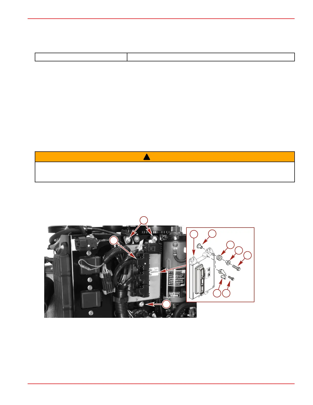
Propulsion Control Module (PCM) Removal and Installation
PCM Removal
!
WARNING
Performing service or maintenance without first disconnecting the battery can cause product damage, personal injury, or death
due to fire, explosion, electrical shock, or unexpected engine starting. Always disconnect the battery cables from the battery
before maintaining, servicing, installing, or removing engine or drive components.
1. Disconnect both battery cables from the batteries.
2. Disconnect the engine harness connectors from the PCM.
3. Remove the screw securing the bracket to the PCM.
4. Remove the three screws securing the PCM to the cylinder block.
a - Engine harness connector (3)
b - PCM
c - Bushing (6)
d - Grommet (3)
e - Screw (M6 x 25) (3)
f - Screw (M6 x 14)
g - Fuse holder bracket

 Loading...


