Direct Fuel Injection
Page 3B-74 90-8M0050731 MAY 2011
12. Remove the two screws securing the air compressor to the top of the cylinder block.
a - Screw (M8 x 25, flange) (2)
Air Compressor Disassembly
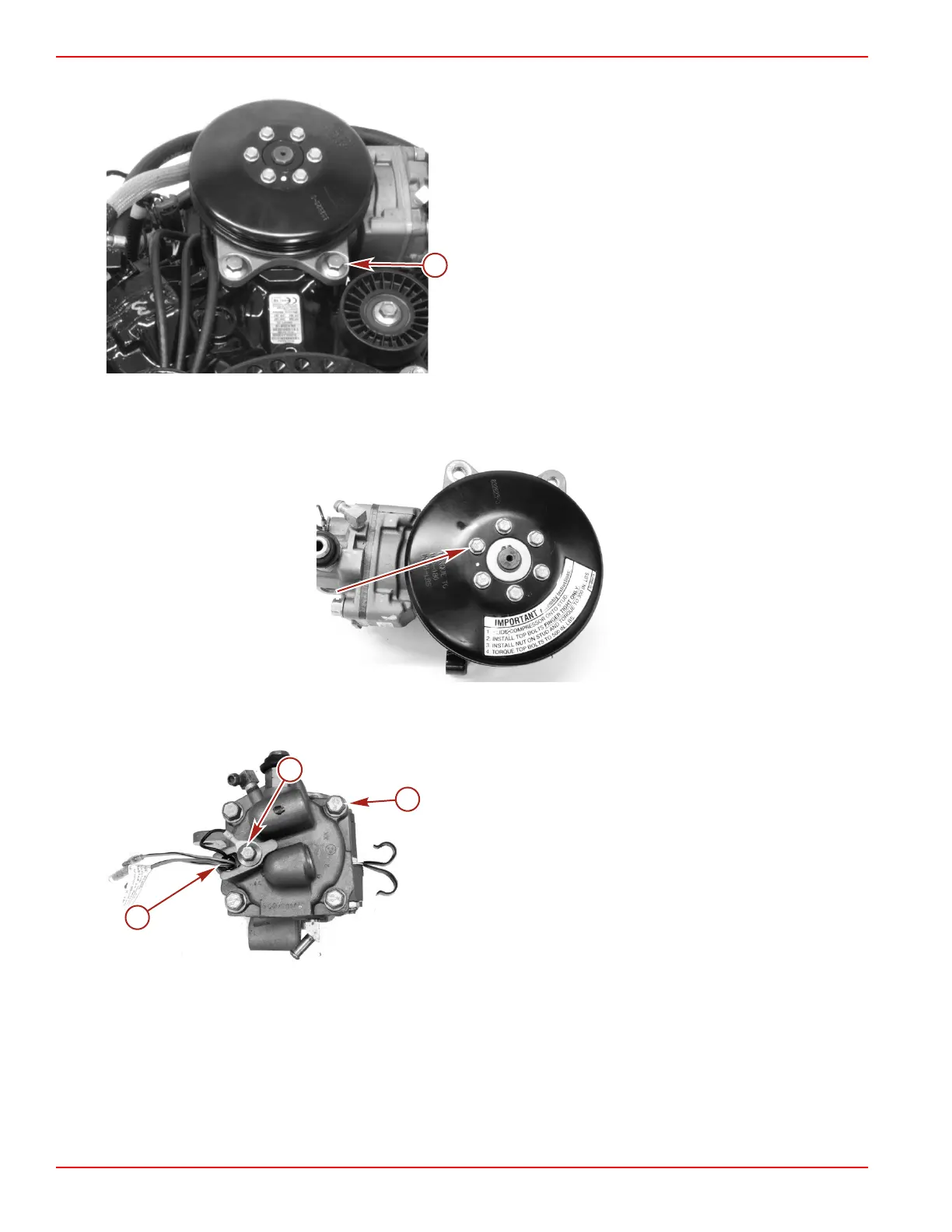
1. Use a strap wrench to hold the air compresser pulley and remove the six screws securing the pulley to the air compressor
crankshaft.
2. Remove the screw securing the air compressor temperature sensor. Remove the sensor.
3. Remove the four screws securing the air compressor cylinder head to the cylinder block. Remove the cylinder head.
a - Air compressor temperature sensor
b - Screw
c - Screws securing the air compressor cylinder head

 Loading...


