Powerhead
90-8M0050731 MAY 2011 Page 4A-63
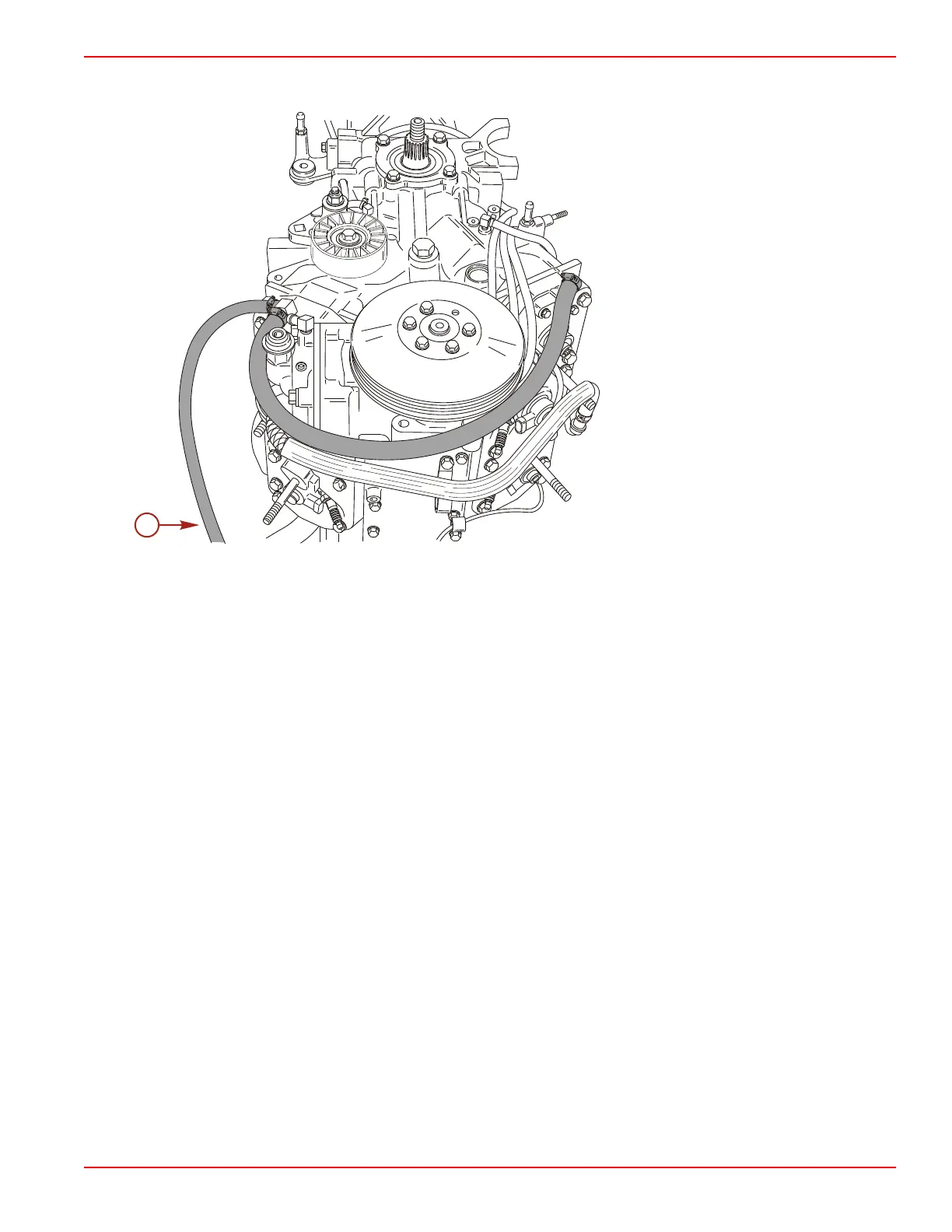
Water Bypass Hose Routing
a - Water bypass hose to through‑the‑hull
fitting
Installing Powerhead Components
Installing Individual Engine Components
NOTE: Engine components can be installed individually or in some cases as an assembly. If installing components individually,
refer to the following sections.
1. Refer to Section 2A - Ignition to install the following components:
• Flywheel cover
• Electronic control module
• Ignition coils
2. Refer to Section 2B - Charging and Starting System to install the following components:
• Flywheel
• Alternator
• Starter motor
• Starter solenoid
3. Refer to Section 3A - Fuel Pump to install the following components:
• Fuel lift pump
4. Refer to Section 3B - Direct Fuel Injection to install the following components:
• Air plenum
• Oil pump
• Fuel rails

 Loading...


