Direct Fuel Injection
90-8M0050731 MAY 2011 Page 3B-75
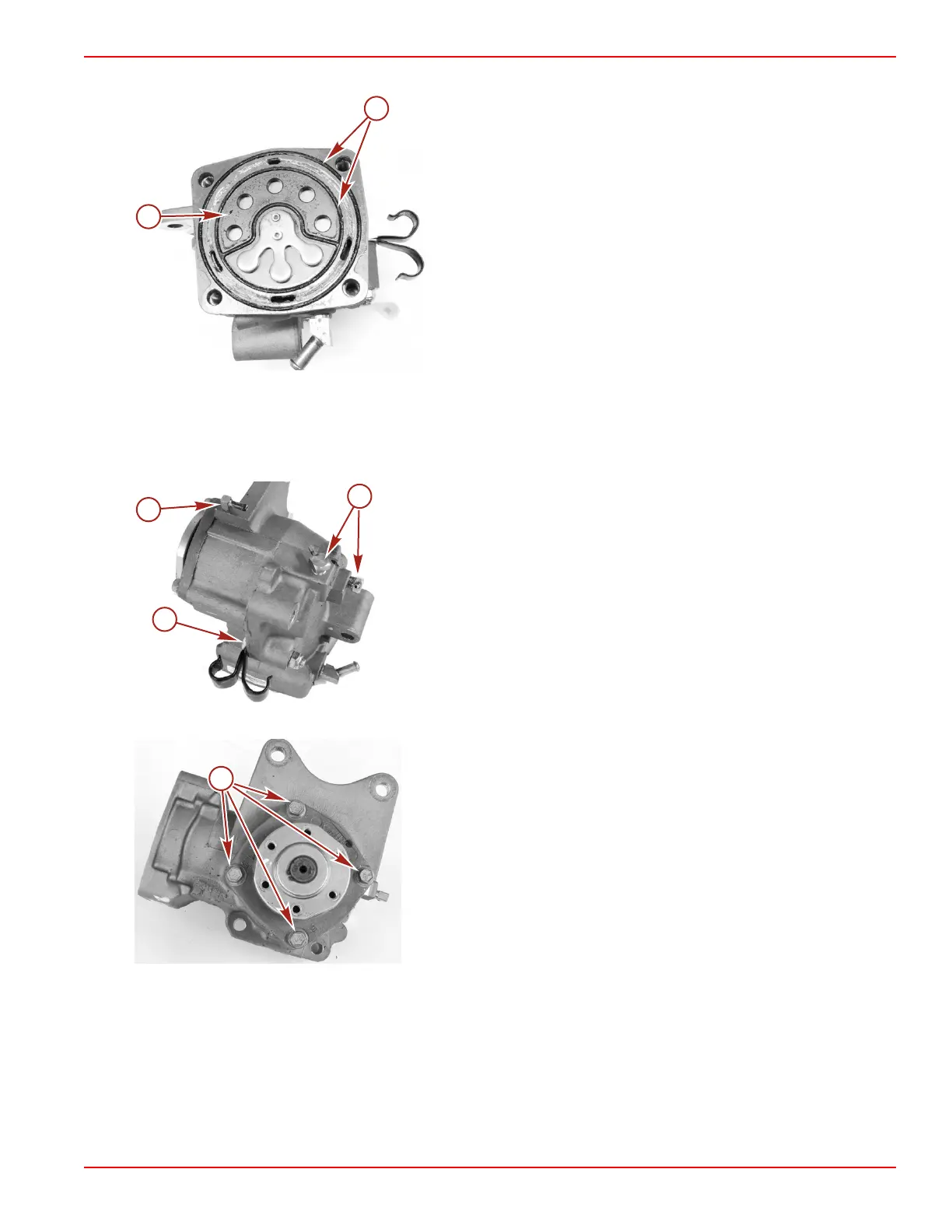
4. Remove the reed plate assembly and O‑rings.
a - Reed plate
b - O‑rings
5. Remove the check valves and fittings.
6. Remove the bolt and nut securing the two J‑clamps.
NOTE: Later models will not use a bolt and nut to secure the J‑clamps. The J‑clamps will be replaced by a plastic clip or cable
ties.
IMPORTANT: Do not remove the air compressor oil supply fitting.
a - Bolt and nut securing the two J‑clamps
b - Oil supply fitting
c - Check valves (2)
7. Remove the four screws securing the air compressor end cap. Remove the end cap.
a - Screw (4)
8. Push the piston connecting rod assembly out of the air compressor.
Air Compressor Assembly
1. Clean the threaded holes on the air compressor with a M6 x 1.0 tap and solvent to remove debris and oil. Clear the threaded
holes with compressed air.
2. Install the rings onto the piston. Stagger the piston rings so they do not line up with each other.
3. Lubricate the air compressor cylinder bore with 2‑cycle Premium Outboard Oil.

 Loading...


