Direct Fuel Injection
90-8M0050731 MAY 2011 Page 3B-63
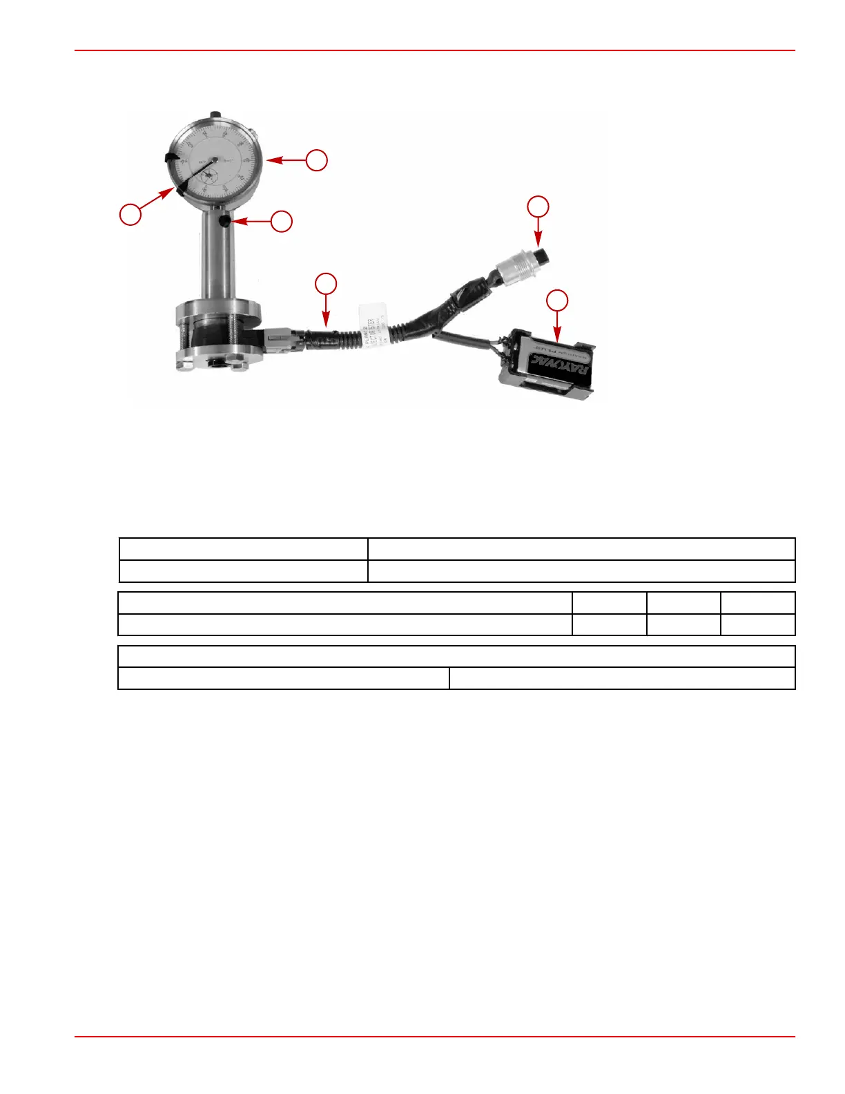
12. Note the dial indicator reading when the direct injector is actuated. The dial indicator measures the direct injector tip movement.
The dial indicator measurement should be within specification.
a - Dial indicator
b - Screw
c - Harness
d - Button
e - 9 V battery installed
f - Dial indicator set at zero
Pintle Test Fixture 91‑899883A08
Dial Indicator 91‑ 58222A 1
Description Nm lb‑in. lb‑ft
Screw 1.7 15
Direct Injector Specification
Direct injector pintle movement 0.020–0.031 mm (0.008–0.012 in.)
13. If the test result is not within specification, the direct injector is defective.
Fuel Pressure Regulator Removal
1. Remove the four screws securing the fuel pressure regulator cover and 4.5 kg (10 lb) spring to the fuel rail.
2. Inspect the fuel pressure regulator diaphragm for damage.

 Loading...


