Jet Installation
90-8M0050731 MAY 2011 Page 1D-35
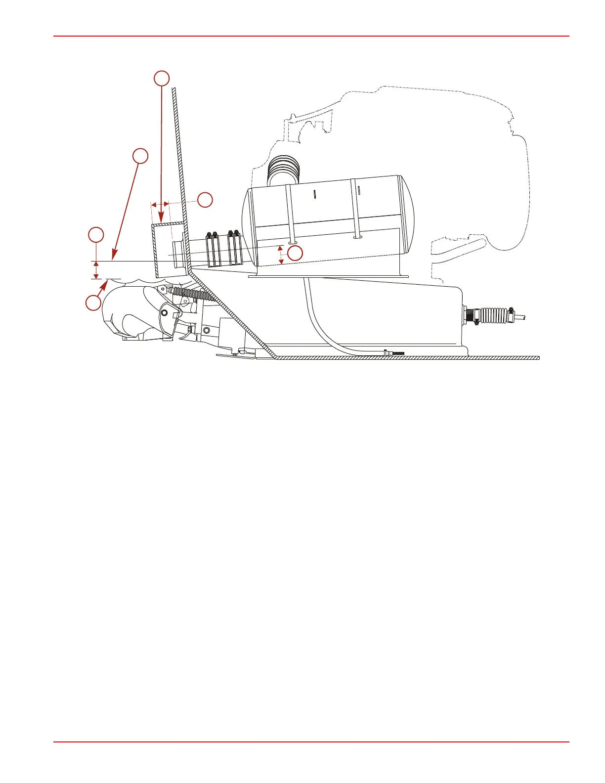
Side View
a - Bottom edge of the muffler outlet tube
b - 5.1 cm (2.0 in.)
c - Waterline
d - Covers
e - 5.1 cm (2.0 in.)
f - 5° outlet angle
• Measure the bottom edge of the muffler outlet tube to ensure that the lowest possible location of the bottom edge of the muffler
tube never gets within 5.1 cm (2.0 in.) of the maximum depth waterline.
• When installing muffler assemblies, a 5.1 cm (2.0 in.) minimum distance between bottom of muffler and waterline must be
kept. This minimum distance must be calculated with boat under its maximum load. Tilt muffler assemblies back towards
outlet to ensure self‑draining.
• Covers may be placed over exhaust outlets to reduce exhaust noise and may extend 10 cm (5 in.) or less below waterline
when boat is at rest.

 Loading...