Direct Fuel Injection
90-8M0050731 MAY 2011 Page 3B-47
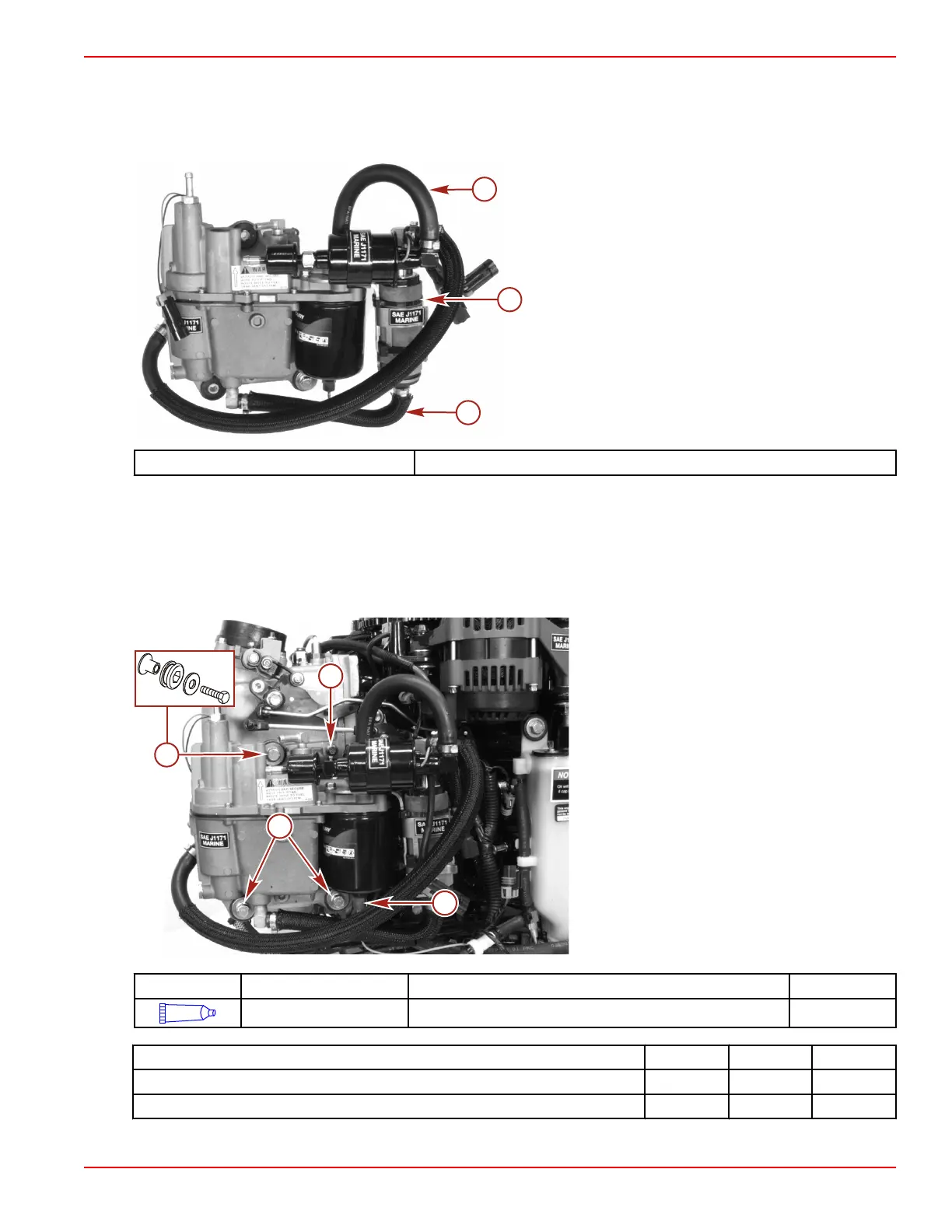
17. Install two 18.3 mm hose clamps onto the low‑pressure electric fuel pump outlet fuel hose.
18. Install the fuel hose onto the fittings. Crimp the 18.3 mm hose clamps with the hose clamp tool.
19. Install two 18.3 hose clamps onto the lift pump to water separating filter fuel hose.
20. Install the fuel hose onto the VST fittings. Crimp the 18.3 mm hose clamps with the hose clamp tool.
a - Lift pump to water separating filter fuel hose
b - Cable tie
c - Low‑pressure electric fuel pump outlet fuel hose
Hose Clamp Tool Kit 91‑803146A04
VST Installation
1. Secure the VST to the plenum with three M8 x 35 screws and washers. Apply Loctite 242 Threadlocker to the threads of the
VST mounting screws. Tighten the screws to the specified torque.
2. Secure the VST ground wire to the plenum with a M6 x 10 screw. Apply Loctite 242 Threadlocker to the threads of the VST
ground wire screw. Tighten the screw to the specified torque.
3. Connect the engine harness water sensor connector to the water separator fuel filter.
a - Screw and washer (3)
b - Ground screw
c - Water sensor connector
Tube Ref No. Description Where Used Part No.
66
Loctite 242 Threadlocker VST mounting screw threads, VST ground wire screw threads 92-809821
Description Nm lb‑in. lb‑ft
VST mounting screws (M8 x 35) (3) 16 142
Ground screw (M6 x 10) 3.5 31
4. Connect the low‑pressure fuel boost pump and the lift pump connectors to the engine harness connectors.

 Loading...


