Charging and Starting System
Page 2B-34 90-8M0050731 MAY 2011
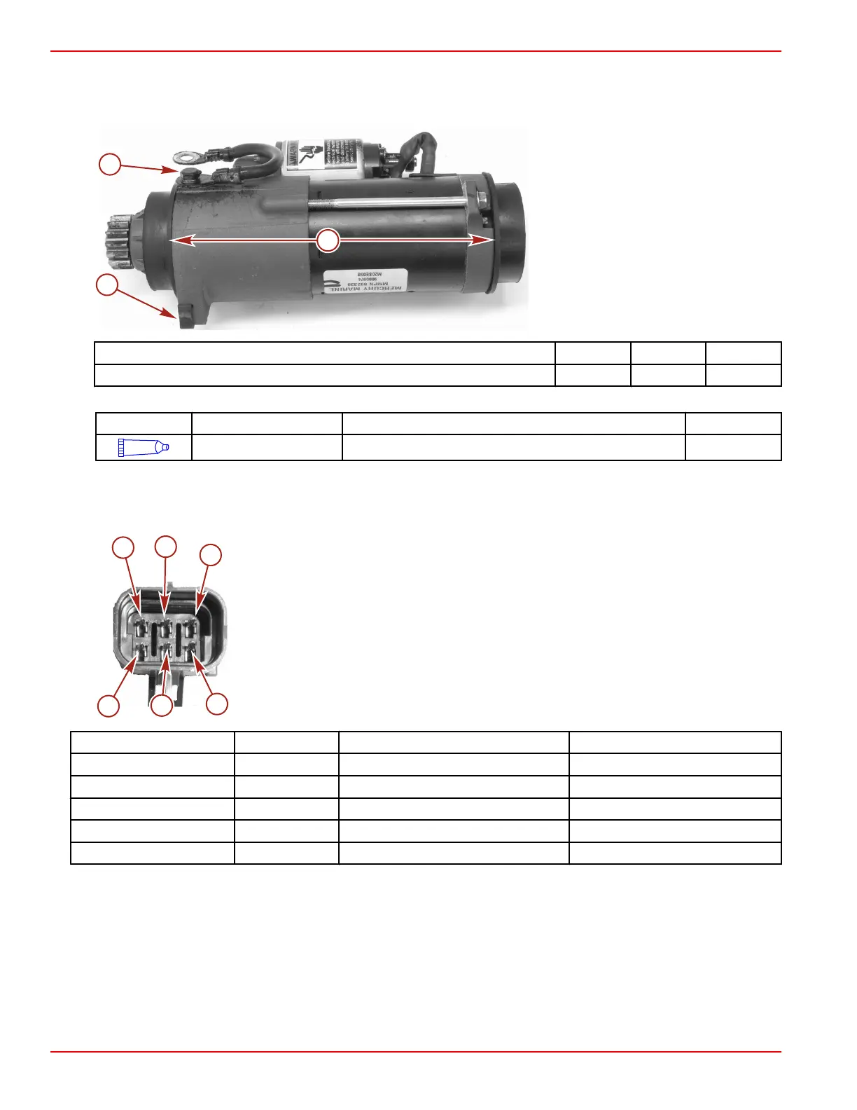
7. Install the two collars and the rubber stops.
8. Secure the starter ground wire with a 0.250‑20 x 0.625 stainless steel screw and washer. Tighten the screw to the specified
torque. Apply Liquid Neoprene to the connection to prevent corrosion.
a - Rubber stops (2)
b - Collars (2)
c - Screw securing ground wire
Description Nm lb‑in. lb‑ft
Stainless steel screw and washer (0.250‑20 x 0.625) 11 97
Tube Ref No. Description Where Used Part No.
25
Liquid Neoprene Starter ground wire connection 92- 25711 3
Key Switch Test
Three Position Key Switch
a - Pin A
b - Pin B
c - Pin C
d - Pin D
e - Pin E
f - Pin F
Ref. No. Pin Wire Color Description
a A Red 12 volts
b B Black Ground
c, d C, D Purple Run
e E Black/yellow Off
f F Yellow/red Start

 Loading...


