Direct Fuel Injection
Page 3B-78 90-8M0050731 MAY 2011
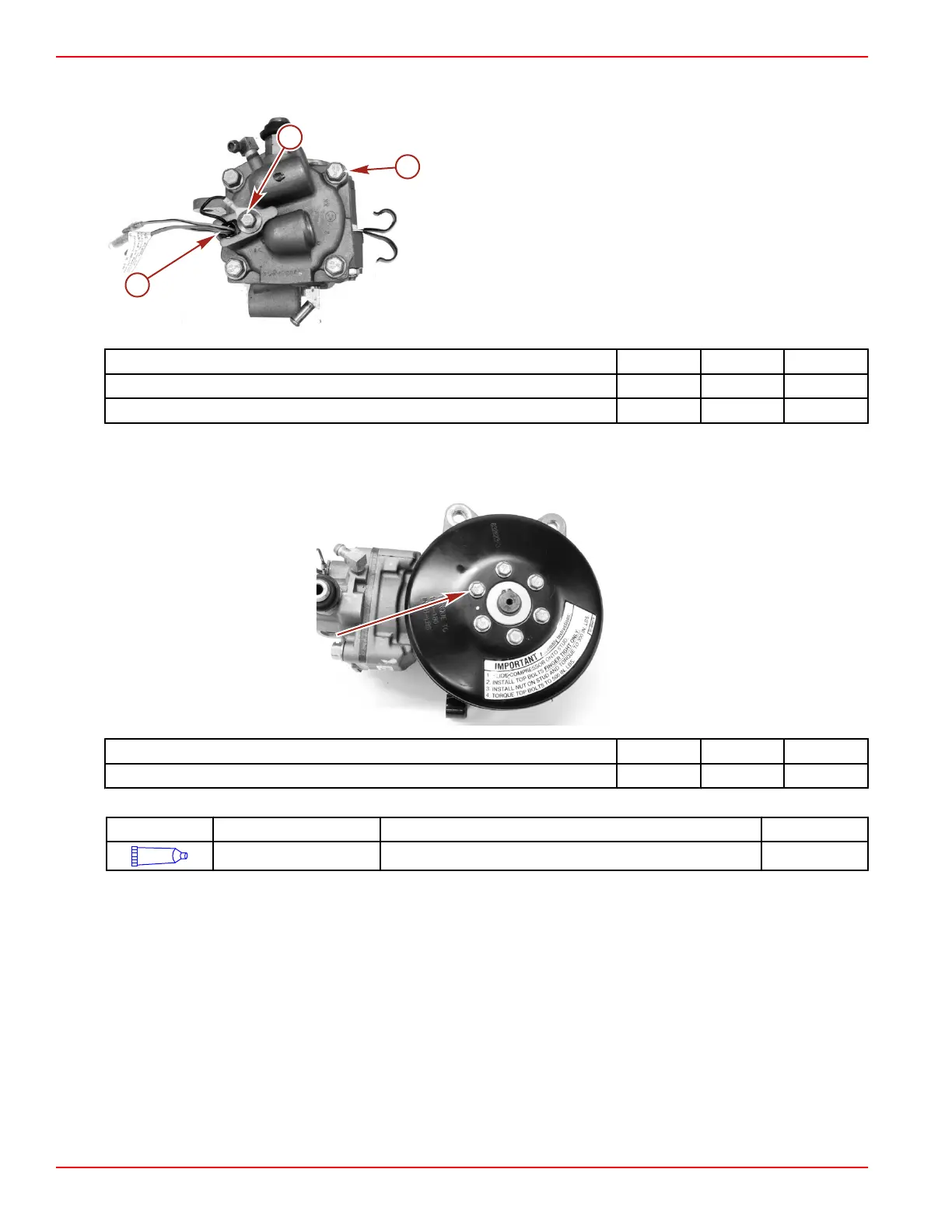
16. Install the temperature sensor ground wire onto the M8 x 14 screw. Secure the temperature sensor with a retainer and the
screw.
a - Air compressor temperature sensor
b - Screw (M8 x 35)
c - Screws securing the air compressor cylinder head (4)
Description Nm lb‑in. lb‑ft
Screws (M8 x 35) 27 20
Screw (M8 x 14) 27 20
17. Install the air compressor pulley.
18. Apply Loctite 271 Threadlocker to the six M6 x 12 screw threads and secure the compressor pulley with the screws. Tighten
the screws to the specified torque.
Description Nm lb‑in. lb‑ft
Screw (M6 x 12) (6) 19 170
Tube Ref No. Description Where Used Part No.
7
Loctite 271 Threadlocker Air compressor pulley screw threads 92-809819
Air Compressor Installation
1. Install the oil line coming from the #5 reed block onto the bottom check valve and secure with a cable tie.
2. Install the oil line coming from the top main bearing onto the side check valve and secure with a cable tie.

 Loading...


