Jet Installation
Page 1D-8 90-8M0050731 MAY 2011
Engine Compartment Specifications
Engine Air Requirements at Wide-Open Throttle
Physical Engine Volume
1.
0.260 m
3
/sec (552 ft
3
/min) 40.4 L (1.41 ft
3
)
For serviceability, Mercury Marine recommends allowing an additional 15 cm (6 in.) minimum of clearance between the powerhead
and the engine compartment walls (per side).
Exhaust and Engine Height
IMPORTANT: It is the responsibility of the boat manufacturer, or installing dealer, to properly locate the engine. Improper
installation may allow water to enter the expansion chamber and combustion chambers and severely damage the engine. Damage
caused by water in the engine will not be covered by Mercury Marine Limited Warranty, unless this damage is the result of defective
parts.
The engine must be properly located to ensure that water will not enter the engine through the exhaust system.
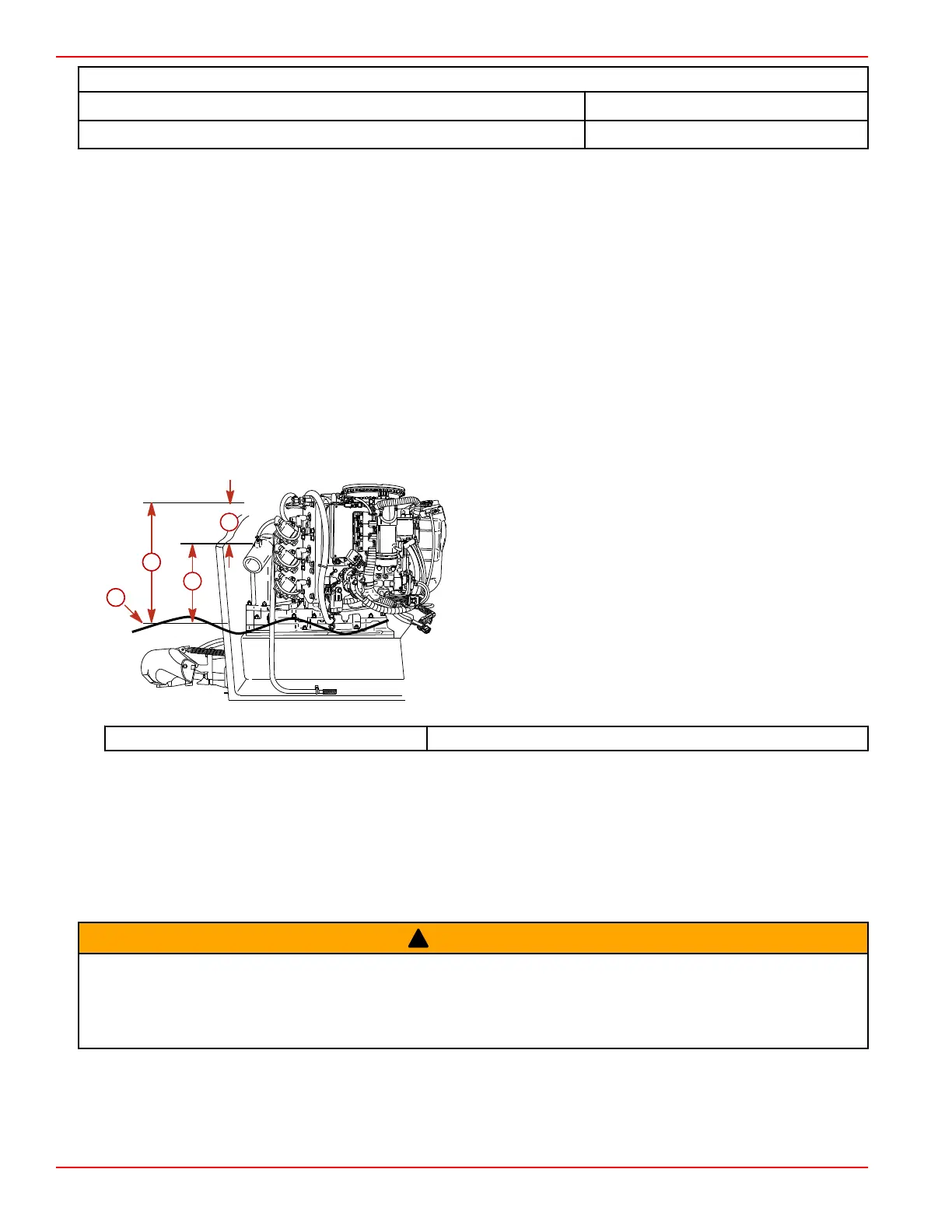
To determine the correct engine height:
1. With the boat at rest in the water and fully loaded, measure between the waterline and the top of the transom measurement
"a."
2. Measure between the highest point on the expansion chamber and the top of the transom measurement "b."
3. Subtract measurement "b" from measurement "a" to find the distance between the highest point on the expansion chamber
and the waterline, when fully loaded. This is measurement "c."
4. Compare results to the chart below. If measurement "c" is less than specified, alter the boat construction to properly lower
the waterline relative to the exhaust chamber.
a - Distance between the waterline and the top of the transom
b - Distance between the highest point on the expansion
chamber and the top of the transom
c - Distance between the highest point on the expansion
chamber and the waterline
d - Waterline at rest (at maximum load)
Measurement "c" 20.3 cm (8 in.) minimum
Fuel Delivery System
Low Permeation Fuel Hose Requirement
Required for Mercury Jet Drives manufactured for sale, sold, or offered for sale in the United States.
• The Environmental Protection Agency (EPA) requires that any Mercury Jet Drives manufactured after January 1, 2009 must
use a low permeation fuel hose for the primary fuel hose connecting the fuel tank to the outboard.
• Low permeation hose is USCG Type B1‑15 or Type A1‑15, defined as not exceeding 15/gm²/24 h with CE 10 fuel at 23 °C
as specified in SAE J 1527 ‑ marine fuel hose.
!
WARNING
Improper boat design and construction may result in serious injury or death. Adhere to all applicable marine regulations (United
States Coast Guard [USCG], European Union–Recreational Craft Directive [EU‑RCD], etc.) and the standards they reference
(American Boat and Yacht Council [ABYC], Society of Automotive Engineers [SAE], International Standards Organization [ISO],
etc.) when designing and constructing the boat and other components, such as the engine compartment, fuel delivery system,
or exhaust system.
1. Fuel pickup should be at least 25 mm (1 in.) from the bottom of the fuel tank to prevent picking up impurities.
2. Fuel lines used must be U.S. Coast Guard approved (USCG type A1), fittings and lines must not be smaller than 8 mm
(5/16 in.) inside diameter.
3. On installations requiring long lines or numerous fittings, larger size lines should be used.
a
d
c
b
5488
1. Physical engine volume is used in flotation calculations and is representative of the amount of flotation the engine provides.

 Loading...


