Pump Unit
90-8M0050731 MAY 2011 Page 5A-25
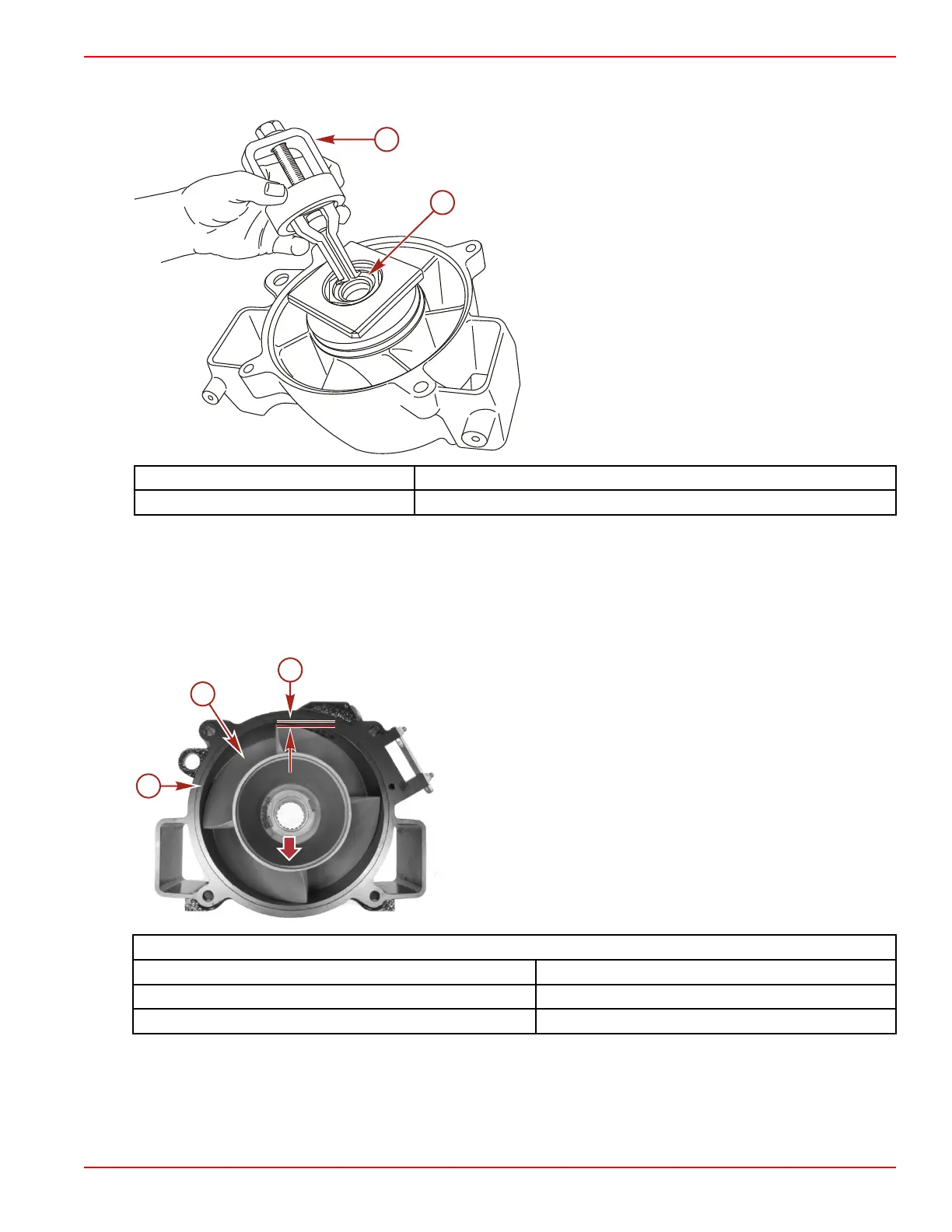
g. Replace the stator seal if required. Use the bearing puller tool to remove the seal. Use the oil seal installation tool to
install the new stator seal.
a - Puller 91‑83165M
b - Stator seal
Bearing Puller Assembly 91‑ 83165T
Oil Seal Installation Tool 91‑850830
Impeller
1. Place the impeller in the wear ring bore and push to one side.
2. Measure the clearance between impeller blades and wear ring with a feeler gauge. If clearance is over 2.54 mm (0.100 in.),
replace impeller and wear ring.
NOTE: Impeller wear usually accounts for 75% of the wear. Reducing the clearance can improve both top speed and
acceleration performance.
a - Clearance
b - Impeller
c - Wear ring
Impeller Component Dimensions
Wear ring bore diameter 184.73–184.98 mm) (7.273–7.283 in.)
Impeller outside diameter 183.52–183.77 mm (7.225–7.235 in.)
Clearance between wear ring and impeller 0.96–1.47 mm (0.038–0.058 in.)
3. Inspect the leading edges of the impeller for nicks and damage. The leading edges should be sharpened to 0.51 mm
(0.020 in.) on the outer half of the leading edge for optimum performance. Dull leading edges can increase cavitation during
initial acceleration.
Impeller and Stator Installation
1. Lubricate the splines of the impeller shaft with Special Lubricant 101.

 Loading...


