Charging and Starting System
90-8M0050731 MAY 2011 Page 2B-25
5. Attach the black cable with the yellow sleeve to the starter solenoid with a M8 nut. Tighten the nut to the specified torque.
Cover the nut with the red boot.
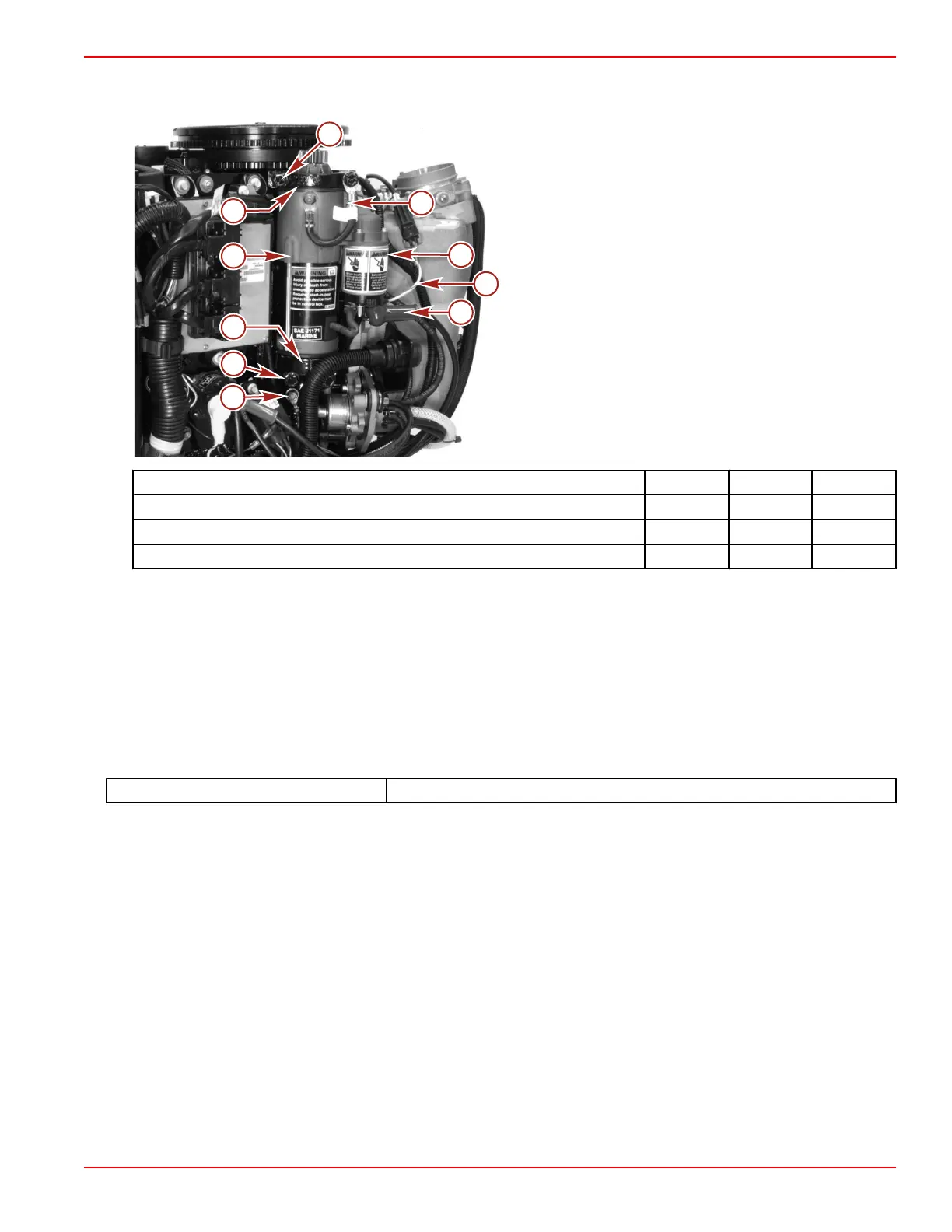
a - Upper mounting bolts (0.312‑18 x 1.50)
b - Bracket
c - Starter motor
d - Cover
e - Lower mounting bolts (0.312‑18 x 2.00)
f - Ground cable
g - Positive cable (black cable with yellow sleeve, M8 nut)
h - Yellow/red wire
i - Starter solenoid
j - Starter ground cable
Description Nm lb‑in. lb‑ft
Mounting bolts (0.312‑18) 24 17.7
Nut (M5) 2.5 22
Nut (M8) 9 80
6. Connect the battery cables to the battery.
Starter Circuit Troubleshooting
Before troubleshooting the starter circuit, verify the following conditions:
• The battery is fully charged
• The remote control lever or tiller handle shift control is in neutral
• All power and ground terminal connections are tight and free of corrosion
• Check all cables and wiring for frayed or worn insulation
• Check all of the fuses related to the operation of the engine
Use the DMT 2004 digital multimeter or an equivalent auto range digital meter for all of the tests.
DMT 2004 Digital Multimeter 91‑892647A01
Some of the tests require the battery voltage be removed from the starter solenoid to prevent unexpected engine cranking.
The following starter circuit troubleshooting chart will assist in locating any malfunction in the starting circuitry. Do not skip any of
the testing sequence procedures unless advised to do so.

 Loading...


