Charging and Starting System
90-8M0050731 MAY 2011 Page 2B-35
Meter Test Leads
Key Position Reading (Ω)
Red Black
Pin B Pin E Off Continuity
Pin A Pin F
Run Continuity
Pin A Pin C, D
Pin A Pin F
Start
Continuity
Pin F Pin C, D Continuity
Pin A Pin C, D Continuity
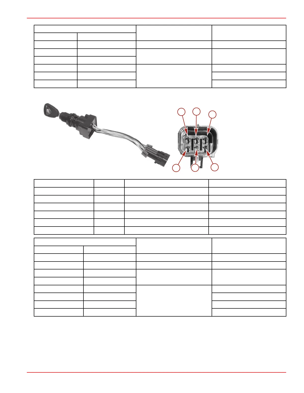
Four Position Key Switch
a - Pin A
b - Pin B
c - Pin C
d - Pin D
e - Pin E
f - Pin F
Ref. No. Pin Wire Color Description
a A Red 12 volts
b B Black Ground
c C Purple/white Accessory
d D Purple Run
e E Black/yellow Off
f F Yellow/red Start
Meter Test Leads
Key Position Reading (Ω)
Red Black
Pin B Pin E Off Continuity
Pin A Pin C Accessories Continuity
Pin A Pin F
Run Continuity
Pin A Pin C
Pin A Pin F
Start
Continuity
Pin F Pin D Continuity
Pin A Pin D Continuity
Pin A Pin C Continuity

 Loading...


