Powerhead
90-8M0050731 MAY 2011 Page 4A-31
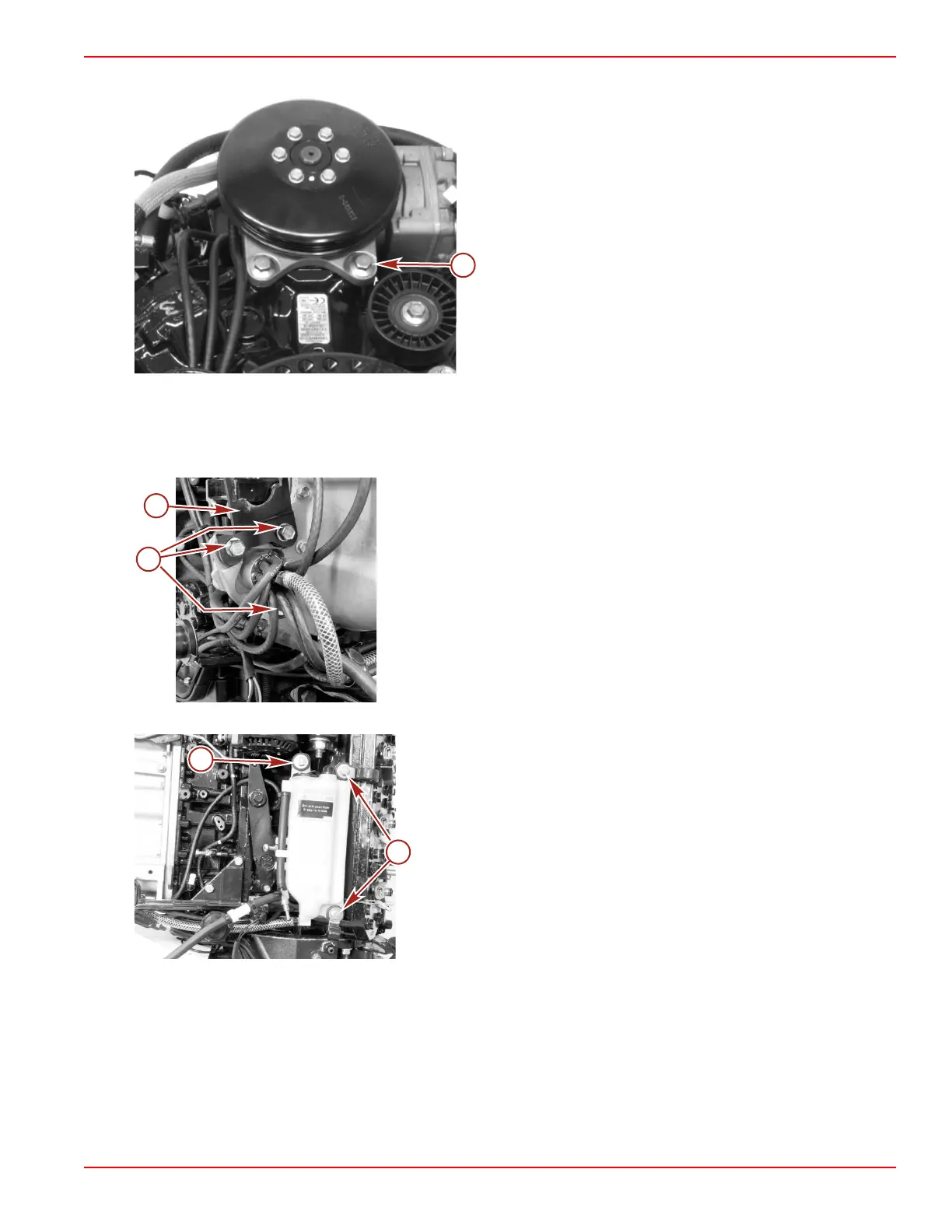
12. Remove the two screws securing the air compressor to the top of the cylinder block.
a - Screw (M8 x 25, flange) (2)
Oil Hoses and Reservoir Removal
1. Remove the three screws securing the 14 pin connector mounting bracket and the oil pump to the plenum.
2. Cut the cable ties securing the oil hoses to the oil pump and remove the oil hoses. Use an appropriate container to capture
the oil that may drip from the oil hoses.
a - 14 pin connector mounting bracket (newer models only)
b - Screws
3. Remove the three screws and washers securing the oil reservoir to the cylinder block.
a - Screw and washer securing oil reservoir
b - Screw and washer securing a clamp and the oil reservoir (2)

 Loading...


