Jet Installation
Page 1D-34 90-8M0050731 MAY 2011
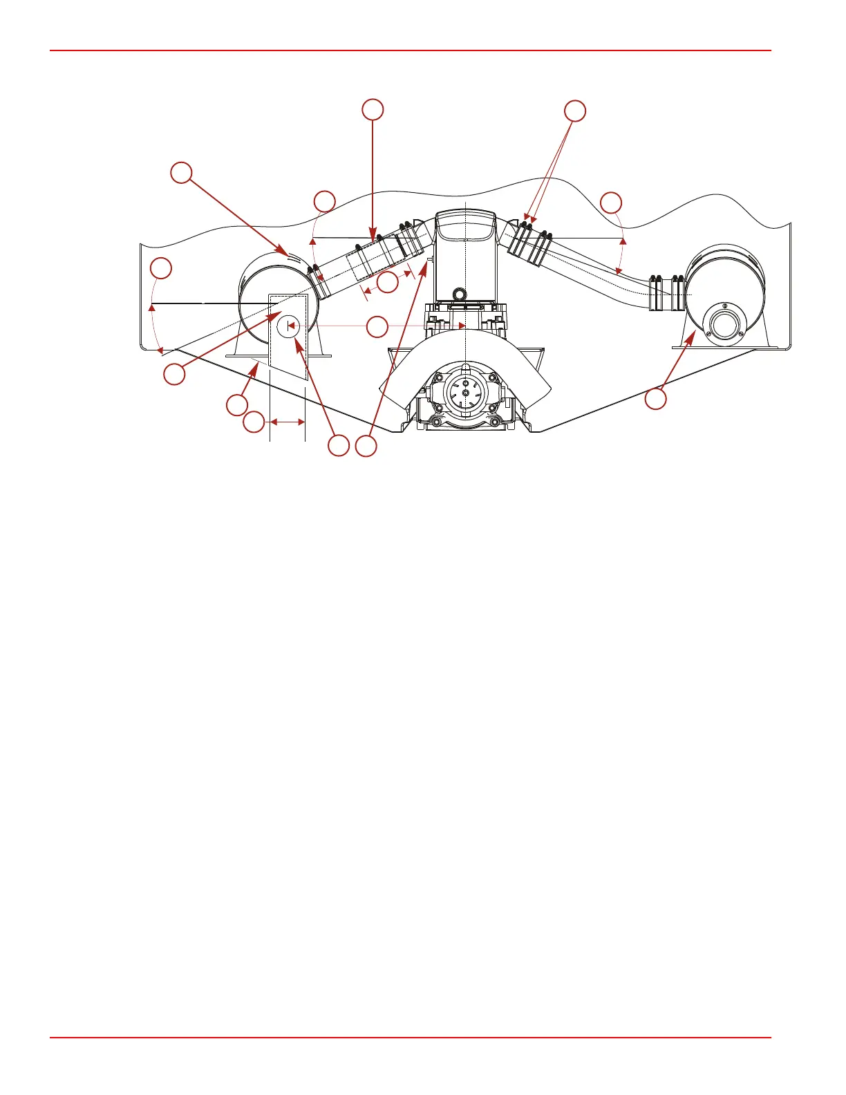
Aft View
a - Alternate installation
b - Typical recommended installation ‑ 54‑815504, 256 stainless steel clamp or equivalent
c - Muffler
d - 25° outlet angle of expansion chamber
e - 15.2 cm (6.0 in.) minimum
f - Reference maximum practical
g - 25° maximum from horizontal
h - Optional exhaust outlet cover
i - 5.1 cm (2.0 in.) minimum
j - 10.2 cm (4.0 in.)
k - Exhaust termination
l - Expansion chamber
m - Rubber mounts
n - 10° minimum angle from expansion chamber outlet to muffler inlet
• If rubber hosing is to be used for connection between the expansion chamber and the muffler, an inner sleeve made of
6061‑T6, 14 gauge aluminum tubing must be used as liner and secured with two stainless steel hose clamps P/N 54‑815504
or equivalent.
• Mufflers may be mounted using straight piping.
• All exhaust hoses and/or tubes must be secured with two clamps at each connection.
• To minimize the backflow of exhaust gases into the cockpit or interior of boat, the exhaust termination should be located as
far outboard of the centerline as practical.
• Final system installation shall be reviewed by a Mercury Marine field representative using a modified expansion chamber to
ensure back pressure does not exceed 10.3 kg (1.8 psi) at 304.8 m (1000 ft) above sea level or less. This test needs to be
performed with the boat in the water and under way. No special loading of the boat is required. However, the engine must be
capable of reaching the specified WOT engine speed. Maximum RPM must be verified using an accurate service tachometer.
• Exhaust system components should be rubber mounted, independently supported, and restrained to minimize noise
transmission to the boat and stress on exhaust system components.
c
l
k
j
i
h
Angled DimensionAngled Dimension
g
g
1.79"
f
m
n
d
a
b
e
5543

 Loading...


