Powerhead
90-8M0050731 MAY 2011 Page 4A-55
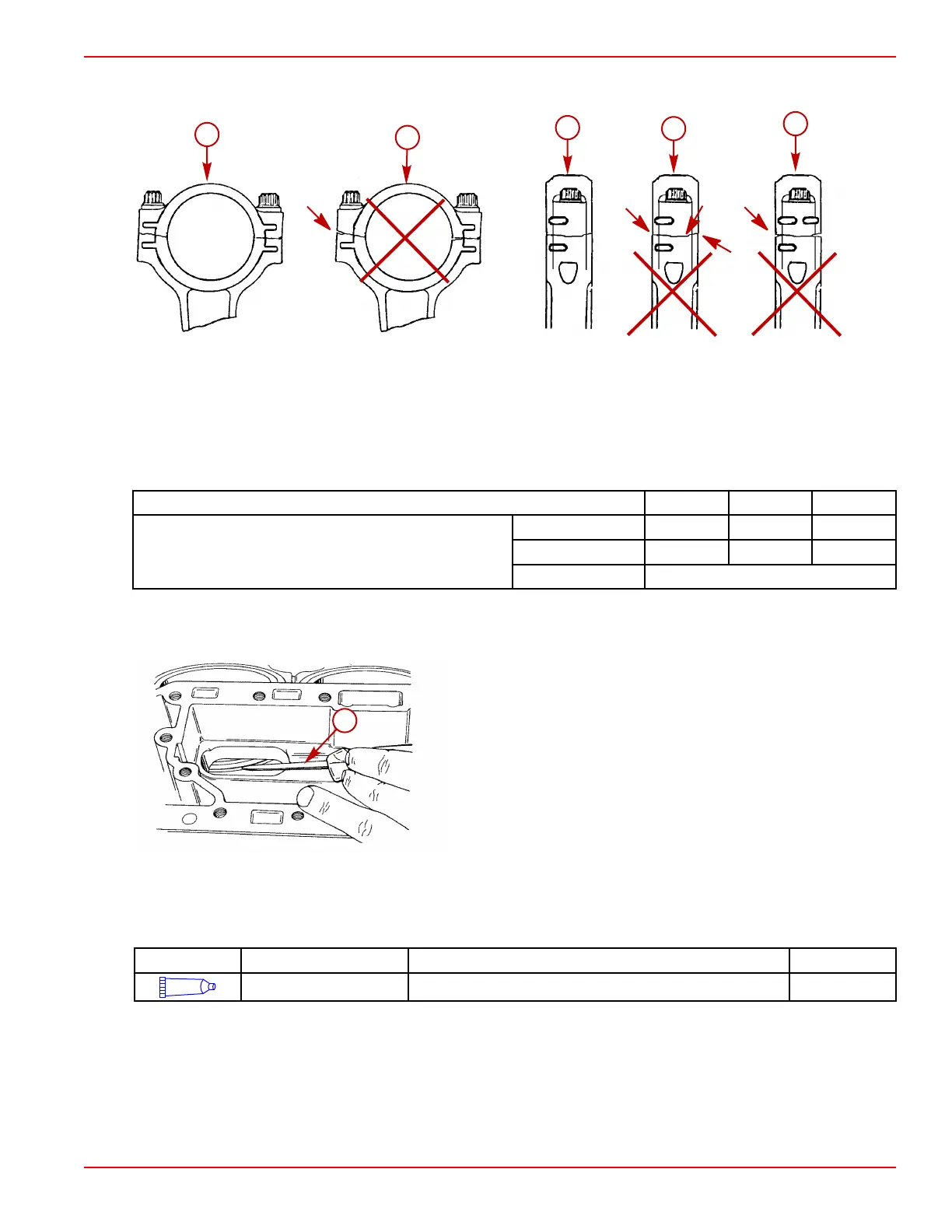
14. Check each connecting rod cap for correct alignment. If it is not aligned, a ridge can be seen or felt at the separating line as
shown below. Correct any misalignment.
a - Side view correct
b - Side view incorrect ‑ cap on backwards
c - End view correct
d - End view incorrect ‑ not aligned
e - End view incorrect ‑ cap on backwards
15. Tighten the connecting rod cap screws in three steps to the specified torque.
Description Nm lb‑in. lb‑ft
Connecting rod cap screw
First
1.5 15
Second
27 20
Final
Turn additional 90°
16. Rotate the crankshaft several revolutions to verify there is no binding or catching.
17. Verify if the piston rings were broken during installation by pressing in on each piston ring through the exhaust port with a
screwdriver. If the ring fails to return to spring back position, it is likely the ring is broken and must be replaced.
a - Screwdriver
Crankcase Cover Installation
1. Ensure the mating surfaces of the crankcase cover and cylinder block are clean.
2. Apply Loctite 7649 Primer N to both of the mating surfaces.
Tube Ref No.
Description Where Used Part No.
117
Loctite 7649 Primer N Crankcase cover and cylinder block mating surface 92-809824
3. Install gasket strips into the grooves in the crankcase cover on S/N 0T178499 and below. Trim the end of each gasket strip
flush with the edge of the cover.

 Loading...


