Powerhead
Page 4A-26 90-8M0050731 MAY 2011
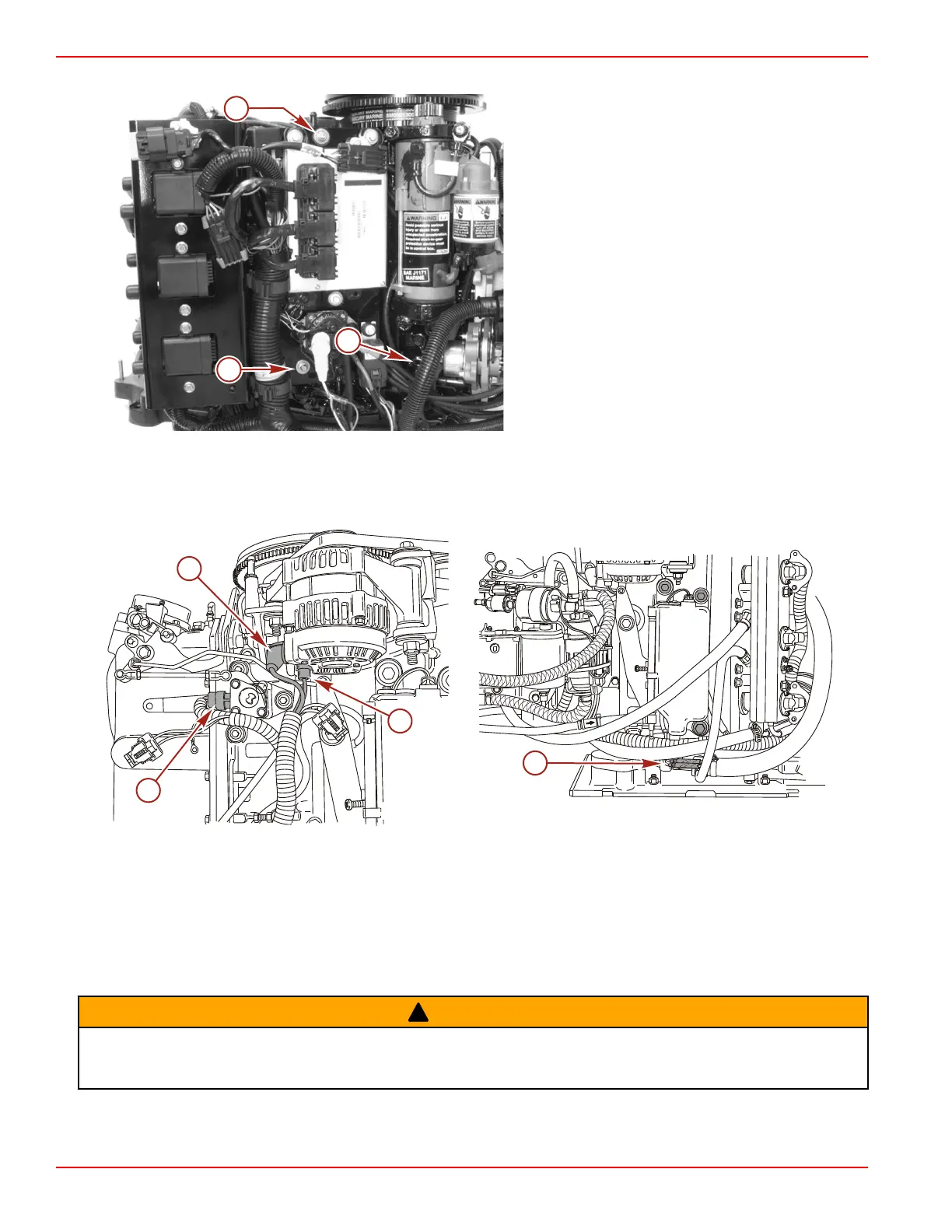
15. Remove the nut and screw securing the electrical plate.
a - Nut and washer
b - Screw
c - Oil pump connector
16. Remove the output lead from the alternator.
17. Disconnect the TPS harness connection.
18. Remove the sense lead from the alternator.
19. Disconnect the low oil sensor bullet connectors.
a - Alternator output lead
b - TPS harness connection
c - Alternator sense lead
d - Low oil sensor bullet connectors
20. Remove the electrical harness assembly from the engine.
Fuel Rail Removal
!
WARNING
Performing service or maintenance without first disconnecting the battery can cause product damage, personal injury, or death
due to fire, explosion, electrical shock, or unexpected engine starting. Always disconnect the battery cables from the battery
before maintaining, servicing, installing, or removing engine or drive components.

 Loading...


