Jet Installation
Page 1D-36 90-8M0050731 MAY 2011
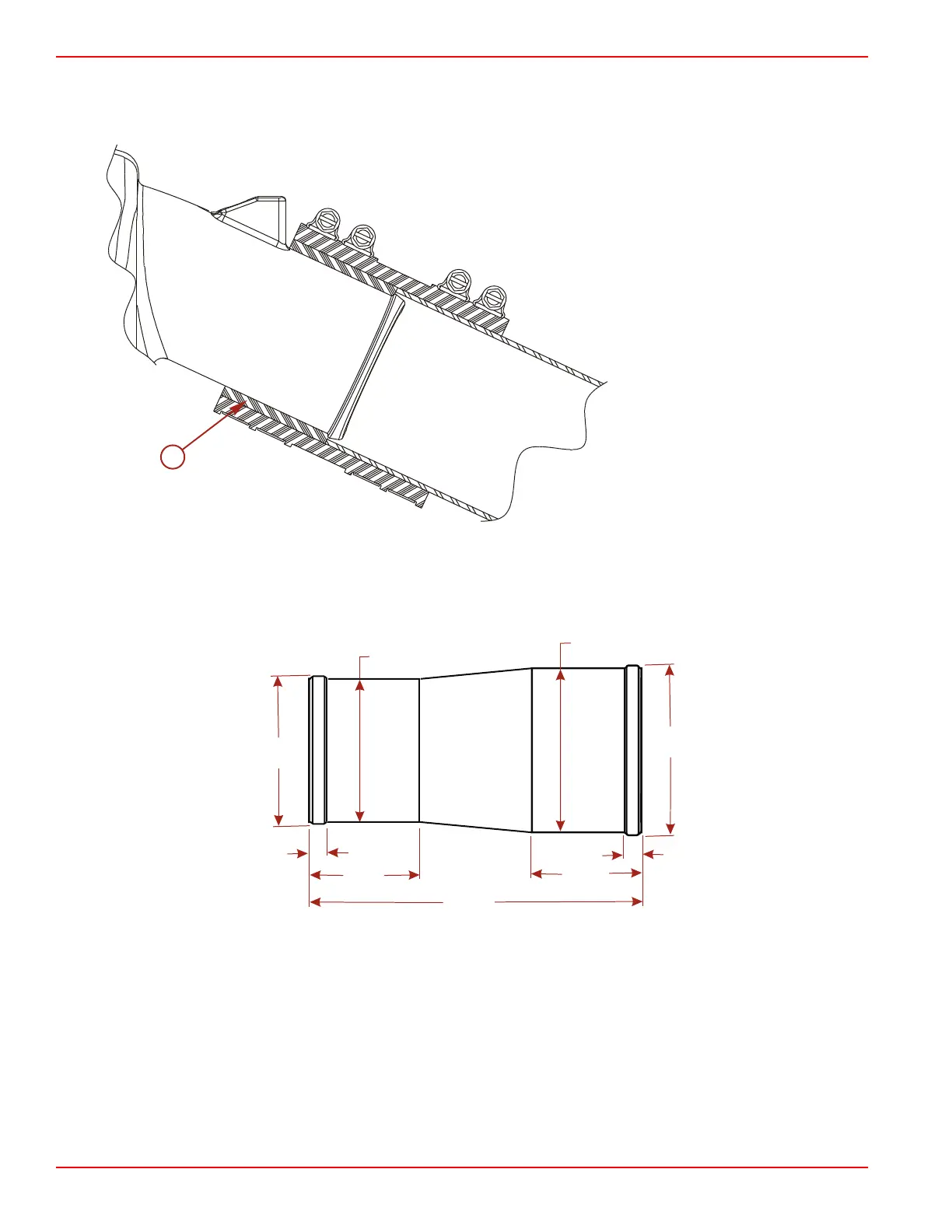
Side View of Expansion Chamber Outlet Pipe and Exhaust Pipe Connection
IMPORTANT: A spacer must be used with all 7.6 cm (3.0 in.) tube applications. A spacer having a 6.73 cm (2.65 in.) I.D. and a
7.6 cm (3.0 in.) O.D. needs to be installed over the expansion chamber outlets.
a - Spacer
Inner Sleeve Liner Fabrication
An inner sleeve liner is required when using a rubber hosing to connect the muffler to the expansion chamber. The inner sleeve
liner gets installed inside the rubber hosing. Refer to Aft View for installation location and requirements.
Material: 6061‑T6, 14 gauge aluminum.
44295
66 mm (2.6 in.)
76 mm (3.0 in.)
78.7 mm
(3.10 in.)
68.6 mm
(2.7 in.)
10 mm
(0.4 in.)
51 mm
(2.0 in.)
152 mm
(6.0 in.)
10 mm
(0.4 in.)
51 mm
(2.0 in.)
Recommended Predelivery Engine Break‑in Procedure
NOTE: Do not use premixed gas and oil in this engine. Use straight gasoline during break‑in and after engine break‑in.
The recommended predelivery engine break‑in procedure for the sport jet engine is important to ensure proper performance and
maximum life from the engine. The following break‑in procedure allows the pistons to ease into conformance with the cylinder
bore.
The engine automatically receives extra oil during the first hours of operation. This extra oil mode will complete in about ten hours.

 Loading...


