Charging and Starting System
Page 2B-8 90-8M0050731 MAY 2011
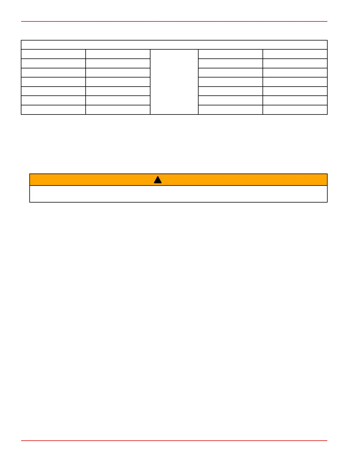
Wire Color Code Abbreviations
Wire Color Abbreviations
BLK Black
BLU Blue
BRN Brown GRY Gray
GRN Green ORN or ORG Orange
PNK Pink PPL or PUR Purple
RED Red TAN Tan
WHT White YEL Yellow
LT or LIT Light DK or DRK Dark
Battery
Battery Cable Test
This test is used to determine if there is excessive resistance in the battery's positive or negative cables, or if the cable is sized
properly to carry the necessary current needed to crank the engine at the proper RPM.
IMPORTANT: This test must be performed while the key switch is in the "START" position. Ignore any voltage readings taken
without the circuit under load.
!
WARNING
Moving parts can cause serious injury or death. Wear eye protection and keep hands, hair, and clothing away from moving parts
when performing tests or checking adjustments on an operating engine.
1. Perform a load test on the battery following the instructions supplied with the load tester. Ensure the battery is brought to a
full charge after being tested.
2. With the key switch in the "START" position, measure the voltage across the battery posts, not the cable clamps. Record the
voltage reading. If the voltage is less than 10 VDC, replace the battery.
NOTE: The voltage reading in step 2 is the base voltage. The base voltage reading will be compared to the voltage readings
obtained in the following steps.
3. With the key switch in the "START" position, measure the voltage from the battery positive post (not the cable clamp) to the
starter post (the stud where the battery positive cable is connected). Record the voltage reading.
4. With the key switch in the "START" position, measure the voltage from the starter case to the battery negative post (not the
cable clamp). Record the voltage reading.
5. If the voltage reading in step 3 was more than 1.0 VDC:
a. Check the cable connections for tightness and corrosion.
b. If the cable is tight and not corroded, replace the cable with a larger diameter cable.
6. If the voltage reading in step 4 was more than 1.0 VDC:
a. Check the cable connections for tightness and corrosion.
b. If the cable is tight and not corroded, replace the cable with a larger diameter cable.
Resistance in the cables can cause a voltage drop and limit current to the starter. If corrosion is present, or if the starter is worn,
there may not be enough amperage to turn the starter motor.
NOTE: If the voltage at the starter is less than 11 VDC, the engine may not start.
Battery Cable Size for Outboard DTS Models
IMPORTANT: Only use copper battery cables. Do not use aluminum cables for any outboard marine installations.

 Loading...


