Charging and Starting System
Page 2B-16 90-8M0050731 MAY 2011
3. Turn the ignition key to the "ON" position. The DMT should indicate battery voltage. If battery voltage is not present, check
the purple lead for a loose or dirty connection, damaged wiring, or a malfunctioning main power relay.
a - Excitation circuit purple lead
b - Alternator ground
Current Output
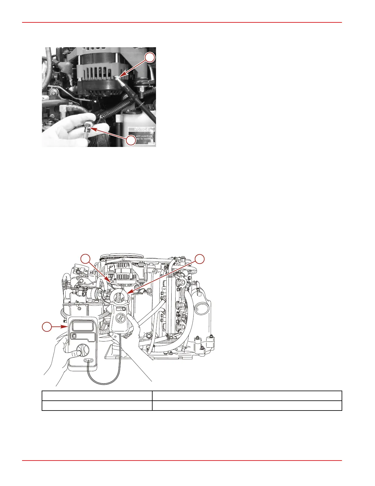
IMPORTANT: Before conducting current output test, ensure that all boat electrical accessories are turned off.
1. With the engine shut off, install ammeter with clamp‑on current probe (capable of reading 60+ amperes) onto the alternator
charging conductor (10 AWG red wire).
2. Start the engine and allow to warm up.
3. Battery voltage should be between 14.0 and 15.0 VDC for all engine RPM's.
4. Supply an external load to the battery until the battery voltage drops to 13 volts or less.
5. Alternator output current should correspond with the table below.
a - Ammeter (DMT 2004 digital tachometer
multimeter)
b - Clamp‑on current probe
c - Alternator charging conductor (10 AWG
red wire)
DMT 2004 Digital Multimeter 91‑892647A01
Clamp‑on Current Probe 91‑802650 1
DCAZEROADJ
LOWBAT
O
F
F
40
4
0
0
ON
OFF
18.5
45593
c
b
a

 Loading...


