Ignition
Page 2A-18 90-8M0050731 MAY 2011
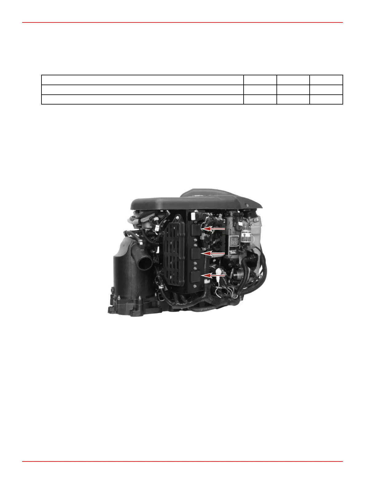
PCM Installation
1. Secure the PCM to the powerhead with the M6 x 25 screws, bushings, and grommets. Tighten the screws to the specified
torque.
2. Secure the bracket to the PCM with a M6 x 14 screw. Tighten the screw to the specified torque.
3. Connect the engine harness connectors to the PCM.
Description Nm lb‑in. lb‑ft
Screw (M6 x 25) (3) 11.5 102
Screw (M6 x 14) 11.5 102
4. Connect the battery cables to the batteries.
Ignition Coils
Ignition Coil Test
The ignition coils used on OptiMax engines use an internal electronic spark trigger (EST) ignition coil driver. Battery voltage is
supplied to the ignition coils and coil drivers when the main power relay is engaged. The crankshaft position sensor sends a
position signal to the propulsion control module. The propulsion control module calculates the exact position of the crankshaft and
determines when to remove the trigger signal from the coil driver of each ignition coil. The coil driver opens the coil primary ground
circuit collapsing a magnetic field across the coil secondary winding which induces a high voltage charge (50,000 volts) that fires
the spark plug.

 Loading...


