Cooling
90-8M0050731 MAY 2011 Page 4B-3
Temperature Sensors
NOTE: The computer diagnostic system (CDS) can be used to monitor temperature readings from both temperature sensors.
Three temperature sensors are used to provide temperature information to the PCM. One sensor is mounted in each cylinder
head (2 pin connector) and one sensor is mounted in the air compressor cylinder head (4 wire sensor). The cylinder head sensors
are threaded into the cylinder head. The air compressor sensor is secured by a retainer and bolt.
The PCM uses this information to increase injector pulse width for cold starts and to retard timing in the event of an overheat
condition.
A resistance test of the temperature sensor would be as follows:
Disconnect the temperature sensor harness and check continuity with digital or analog ohmmeter test leads between both
connector pins. Readings should be within 10% of specified. There should be no continuity between each connector pin and
ground.
DMT 2004 Digital Multimeter 91‑892647A01
Computer Diagnostic System (CDS) Order through SPX
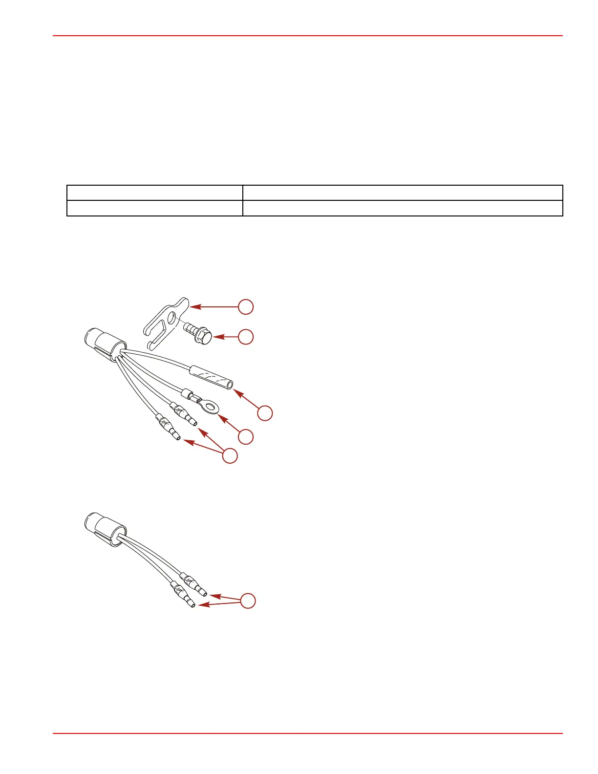
4 and 2 Wire Temperature Sensor
1. 4 wire sensor:
a. Analog gauge sender ‑ tan/blue and black leads
b. Temperature sensor ‑ tan/black leads
c. One sensor installed in the air compressor head
4 wire sensor
a - Tan/black wires ‑ temperature sensor
b - Black wire ‑ analog gauge
c - Tan/blue wire ‑ analog gauge
d - Bolt
e - Retainer
2. 2 wire sensor:
a. Temperature sensor only ‑ tan/black leads
b. One sensor installed in each cylinder head
2 wire sensor
a - Tan/black wires ‑ temperature sensor

 Loading...


