Ignition
Page 2A-14 90-8M0050731 MAY 2011
Theory of Operation ‑ Internal Ignition Coil Driver Models
When the ignition key is turned to the "RUN" position, battery voltage is supplied to the electrical system through the main power
relay. If the propulsion control module (PCM) does not sense engine rotation within a certain time period, the relay is turned off.
Engine rotation will engage the relay. When the main power relay is closed, voltage is supplied through the 20 amp ignition fuse
to the positive terminal on all of the ignition coils. Each coil contains an internal driver circuit. The driver circuit switches the primary
current on for a given time period (dwell), and then switches it off, collapsing the coil magnetic field creating a spark. The crankshaft
position sensor (CPS) reads the position pattern on the flywheel, which allows the PCM to monitor the position of the crankshaft
while the engine is running. At the proper time for ignition spark, the PCM sends a signal to the coil driver to dwell and then provide
spark. When the engine is operating at lower RPM, this process is repeated in quick succession to provide a multi‑strike spark for
each combustion event. The number of strikes per event is varied, depending on RPM and load requirements. The spark plug
irridium electrode and ground extends into the combustion chamber.
Fuses
IMPORTANT: Always carry spare 5 and 20 amp fuses.
The electrical wiring circuits on the engine are protected from overload by fuses in the wiring. If a fuse is open, try to locate and
correct the cause of the overload. If the cause is not found, the fuse may open again.
1. Open the fuse holder and look at the silver colored band inside the fuse. If the band is broken, replace the fuse.
2. Replace the fuse with a new fuse with the same rating.
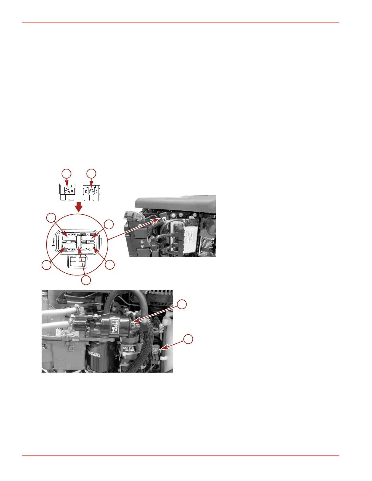
The fuses and circuits are identified as follows:
a - Good fuse
b - Blown fuse
c - SmartCraft data bus circuit ‑ 5 amp fuse
d - Ignition system circuit ‑ 20 amp fuse
e - Spare fuse
f - Electric fuel pump (VST)/ECM driver power/
oil pump circuit ‑ 20 amp fuse
g - Main power relay ‑ 15 amp fuse
a - Lift pump
b - Lift pump circuit ‑ 5 amp fuse

 Loading...


