Pump Unit
Page 5A-28 90-8M0050731 MAY 2011
Tube Ref No. Description Where Used Part No.
66
Loctite 242 Threadlocker Trim plate screws 92-809821
Description Nm lb‑in. lb‑ft
Trim plate screws 8.5 75
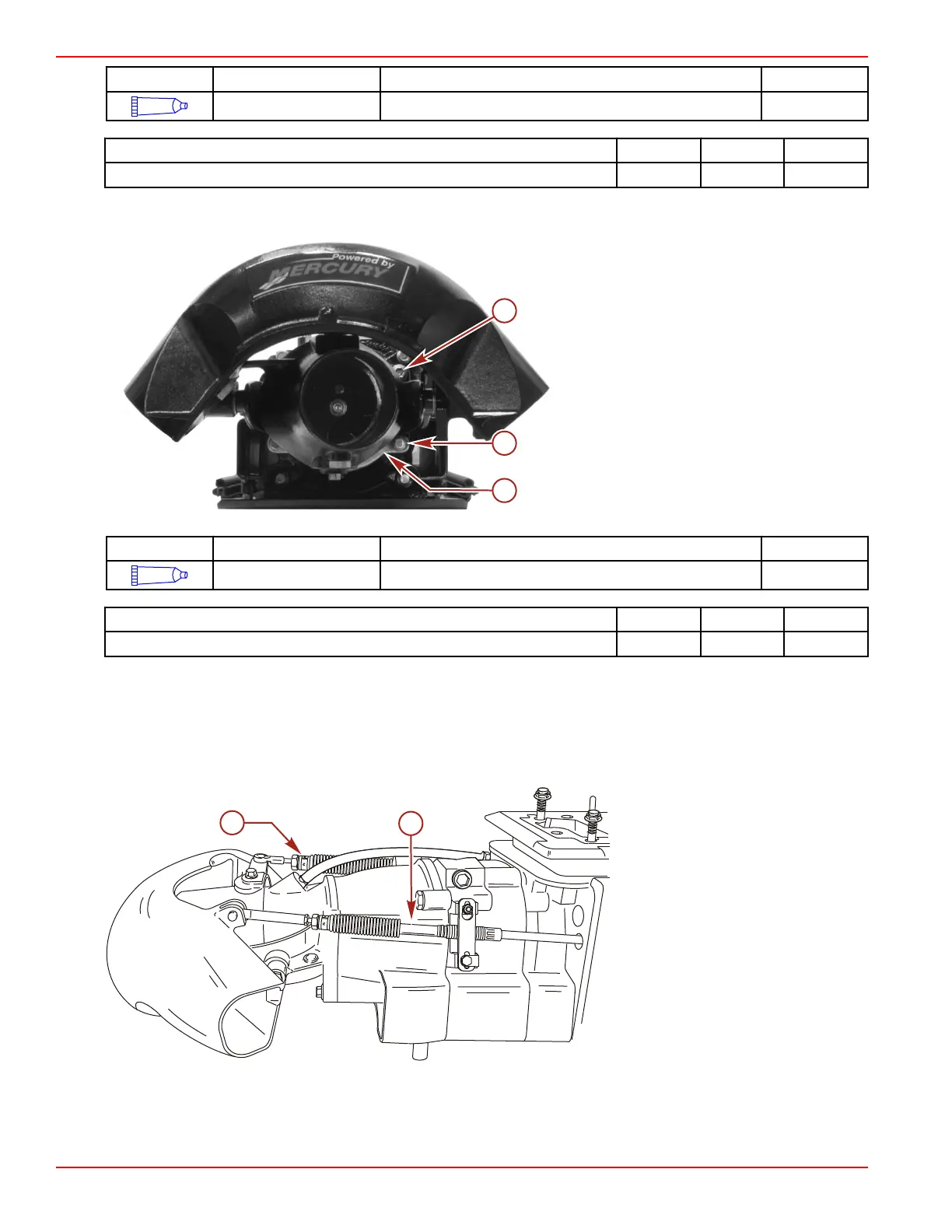
10. Install the nozzle assembly and anode. Apply Loctite 271 Threadlocker to the threads of the screws. Tighten the screws to
the specified torque.
a - Screw (M10 x 35) (2)
b - Screw (M10 x 45) (2)
c - Anode
Tube Ref No. Description Where Used Part No.
7
Loctite 271 Threadlocker Nozzle assembly and anode screws 92-809819
Description Nm lb‑in. lb‑ft
Nozzle assembly and anode screws 47 35
11. Attach the shift and steering cables. Refer to Section 1D.
Removing Jet Drive from Boat
1. Remove the powerhead. Refer to Section 4A - Powerhead Removal from the Pump Unit.
2. Disconnect the shift and steering cables from the reverse gate and rudder. Remove the cable adapters and bellows
assemblies. Loosen the shift and steering cables at the wear ring.
a - Shift cable
b - Steering cable
3. Loosen the shift and steering cable through‑the‑hull fittings.
IMPORTANT: The pump unit must be supported to prevent it from dropping through the opening when the remaining fasteners
are removed.

 Loading...


