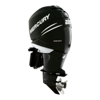
Powerhead
90-8M0050731 MAY 2011 Page 4A-21
9. Remove eleven nuts (five nuts on opposite side) securing the powerhead to the housing cover.
a - M10 nuts (11)
10. Remove the plastic cap from the center of the flywheel and install the lifting eye into the flywheel at least five full turns. Lift
the powerhead assembly from the pump unit.
11. Remove the exhaust outlet coolant hose from the air compressor.
12. Remove six nuts securing the expansion chamber and remove the expansion chamber.
a - Coolant hose
b - Nuts (6)
Removing Powerhead Components
Individual Components
NOTE: Engine components can be removed individually or in some cases as an assembly.
1. Refer to Section 2A - Ignition to remove the following components:
• Flywheel cover

 Loading...


